As you can see in the 3D model, the engines have multiple colors. (Though the number 3 will not be modeled.)
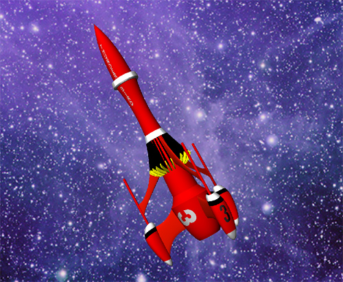
I am printing those in color, not painting them, so I had to cut up the model yet make sure they fit together. Last night I cut them it up so it would fit into the main fin, as well as fit together.
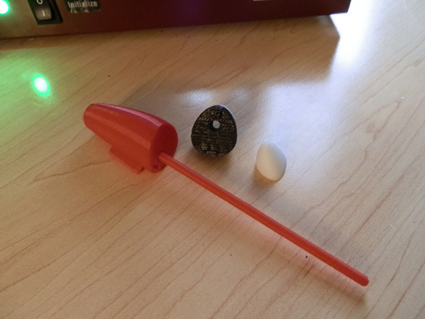
It is not obvious from this rendering, but at the top of the engine is a black intake, a funnel into which the antenna struts go. I have not yet modeled the cylindrical hole to make those fit. I concentrated on making the pieces fit together.
The tricky one was the white top, as it had to act as a cap on a peg that would be both the black stripe and the rocket intake funnel.

Normally I print in the color the part will end up in, but for a quick test fit I just used the red color, so I wouldn’t have to change out the color 3 times, which is a bit time consuming.
These pieces do not yet have pegs to slot them together where they join, so I just SuperGlued them for now. (The final model will also require glue. I’m not making the connections that perfect.)
And here you have the result:
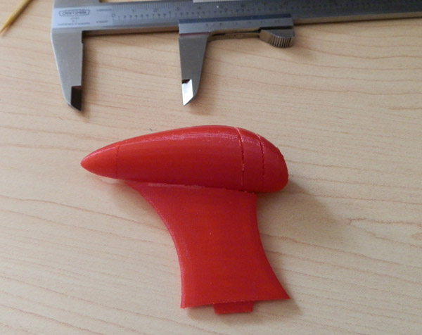
These are printed at .25mm. The final will be .15mm, so the connections between the pieces may be better. But when you print on an angle, you get stepping, and when you have two pieces that have stepping that are supposed to fit together, you hope for the best. With .15mm, the fit should be better than you see here.
Next: Drill a hole down through the engine parts that will fit the engine struts, and redesign the bottom piece to have a rocket cone. Right now it is round, and not a realistic engine. In the concept, that round bottom irised open to reveal a rocket exhaust. My finished model will just have a flat bottom with a cone in black (another snap-fit part I have yet to model.)
Update:
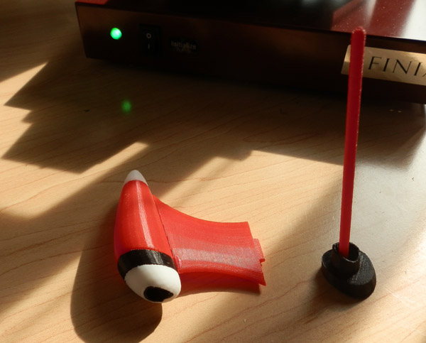
Last night I printed the pieces in color for a new test-fit. Then I began the process of drilling holes into the pieces to fit the antenna struts. This photo shows the engine assembled in color, (without the hole for the strut) and next to it, the top piece (which has the jet intake and the black stripe) with a hole drilled and the antenna strut test-fitted in it.
Next up: Drill a hole in the main body and redesign the slot for the main fin. I didn’t like the way the main fin fit up against the engine housing. Resolution at this level isn’t sufficient to make those pieces fit perfectly, so I’m going to make a slot in the engine for the entire fin connection to fit inside, just a bit, and then I have to redesign the bottom section of the body to do the same. Since that would require reprinting of both the bottom and mid body pieces, I may not do that yet.
But the white bottom piece has to change a bit too, to cut a maneuvering thruster hole there. I am also adding the real rocket engines to the dent in the bottom piece. (Originally the three engines were going to be sufficient, but with small thruster outlets, it made little sense that that could power this rocket. So instead I’m using the bottom divot to install three massive rocket engines. More on that as it develops.
Update 2:
Last night I added tabs and slots to each engine piece so they could slot together nicely for gluing with perfect alignment. The main engine body and the black stripe piece now have holes in them for the engine struts, and they fit perfectly. I redesigned the main fin slot to have a tent roof, rather than flat, because a flat roof requires support material, and a tented one does not. No visible difference, as it’s inside the part.
Here are the pieces, now complete, for this test model:
My next task is to print two more of this, and two more main fins and upper fins, and I can actually fully assemble my rocket as it is now, before I begin adding detail like thrusters and the like.