Concept
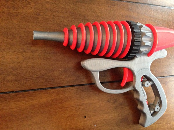
Ok, I’m going to confess that I like this one quite a bit.
I started with some small sketches of retro 50s ray guns. When I sketched one in pencil I quite liked, I redrew it in pen, and colored it with colored pens, on graph paper.
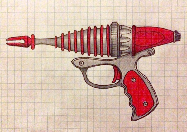
I scanned this image and created an image plane in my 3D modeling software package. I used that as a horizontal guide.
The one thing I didn’t like was the muzzle, so I left that for last, hoping I would come up with a better idea when I got to it.
Assembly
One thing I wanted to do, and added a lot of time to modeling, in this one, was to avoid having to use glue of any kind. This required carefully designing each piece to screw or bolt to previous pieces until it was solidly constructed.
That, and I wanted it to be heavy.
Recently, I created WERBLZ, a series of rolly-aliens, which I hope to make available to the general public soon. To bet these WERBLZ to roll, I used a short carriage bolt.
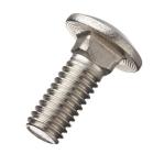
I sheared the rounded head off to use at the bottom of the WERBLZ to make them wobble. That left the bolts as junk, so instead of tossing those, I decided to keep them for weight in various models I wanted to add weight to.
I started with halves of a handle. Since this was a little too large to print on my Afinia H479 and H480 printers, I cut it into two pieces, using a jig-saw method to attach them nice and tightly.
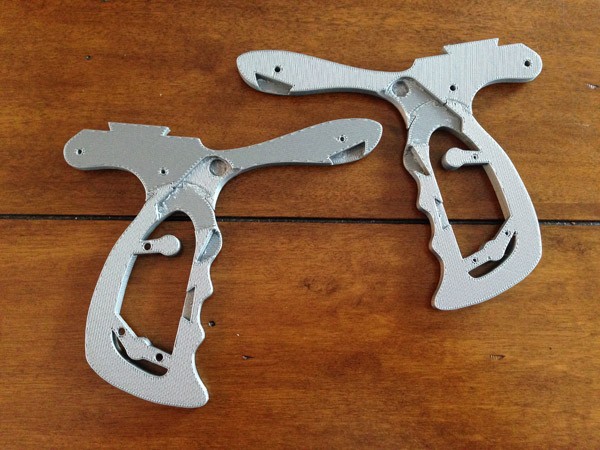
Each half has three screw holes at the top, and three screw holes in the handle itself. Then there were two screw holes to screw the grip panels to.
I needed space to add a trigger, which pulled correctly, and a part for the base of a spring to attach to. This would allow for the trigger to actually work.
Once these elements were placed, the two halves screwed together: (Note I only use two of the three screws to attach the handle halves. No need for the third, but it could be used. I was running short on screws, so I skimped.

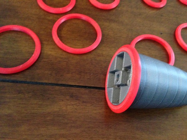
Note the notch at the top, near the rear. This is to slide the body of the gun onto the handle frame. First, the central “heat sink” section is slotted into position:
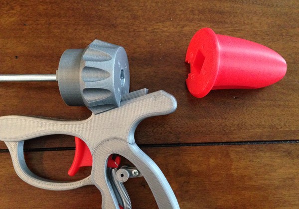
At this point a 6 inch bolt with a hex head is pushed into a space in the heat sink piece. The hex head fits into a hex aperture, while the bolt comfortably (though snugly) fits through the whole piece. The heat sink section acts as a wrench, in a way. I can rotate the barrel on and the bolt will be held in place by the heat sink.
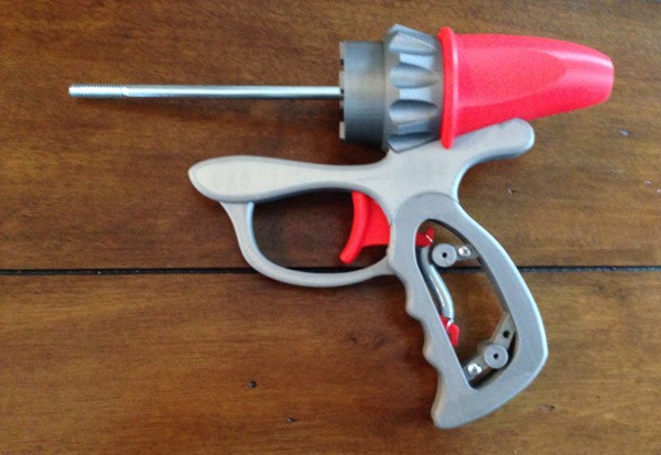
Four screws screw into the front of the heat sink, and drill into the red rear section. Note the square nubs at the front of the heat sink section. These fit into squares in the main barrel so the barrel won’t spin.
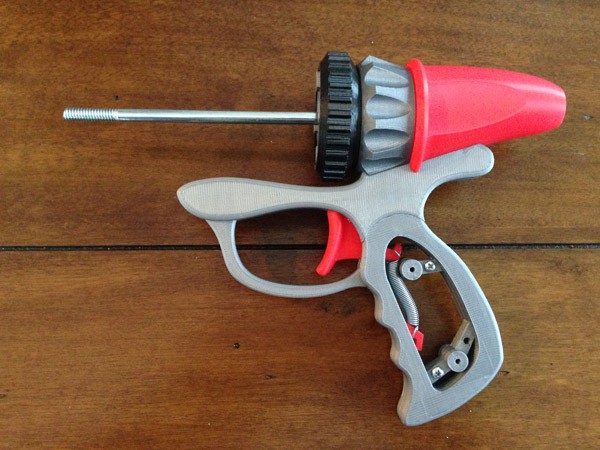
The black dial ring slips over the heat sink, and is allowed to freely rotate. This is a ray intensity dial.
I slipped a bolt inside the rear section for weight too.
Next, the main barrel gets its rings:
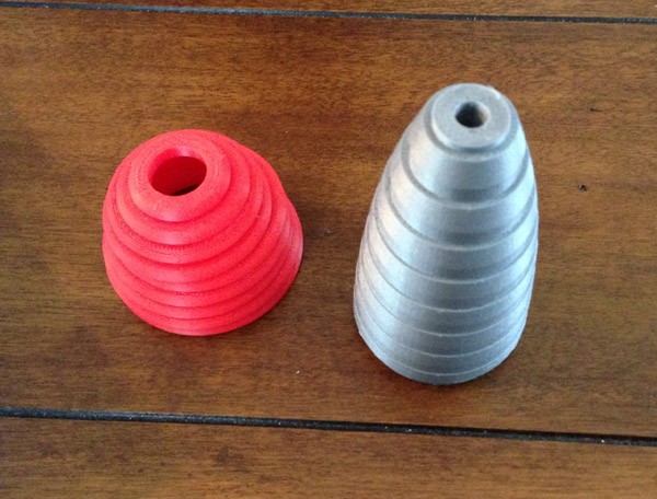
Each of the rings (left) slips over the main barrel cone very snugly.
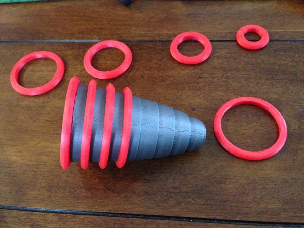
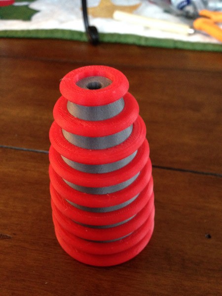
The main barrel is complete when all the red rings are in place:
Here I show the bolt section of the carriage bolt I sheared off eariler (to create the WERBLZ), wrapped in Scotch Tape for friction hold, placed into the main barrel section for heft:

Then, three more:

Then the main barrel is slipped over the long bolt. The four holes for bolts also meet up with four square plugs on the heat sink section to prevent the barrel from rotating.
The barrel neck has a slightly smaller cylindrical aperture, with ridges so the bolt can grab on and act like a nut:
Then the muzzle is attached with a single screw:
Four small pegs/holes in the neck/muzzle keep the muzzle from rotating.
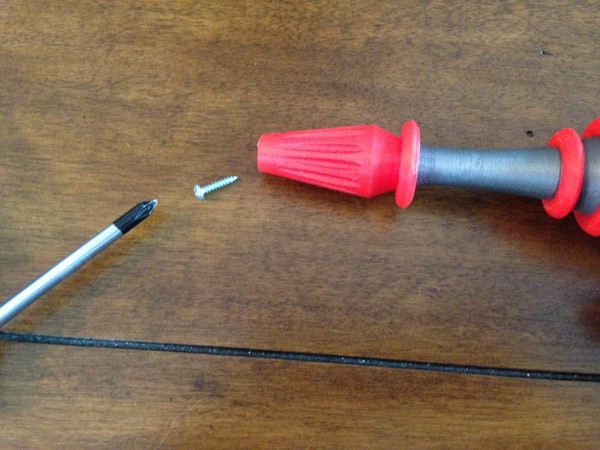
Then the focus dial at the back is added:
A single screw holds the dial on:
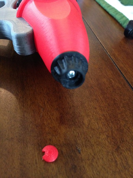
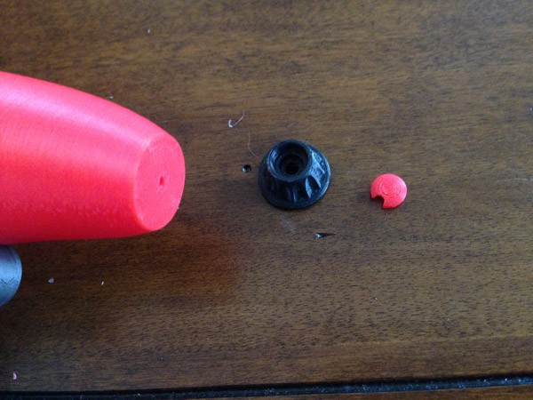
A red plug covers the screw, but has a small notch so it can be easily removed if needed.
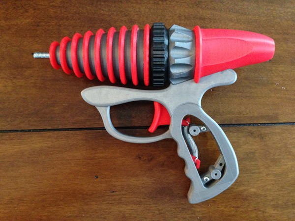
Last, I put one more carriabe bolt in the gap inside the handle frame, for better weight, then the handle grips are screwed onto the handle frame to form the final product:
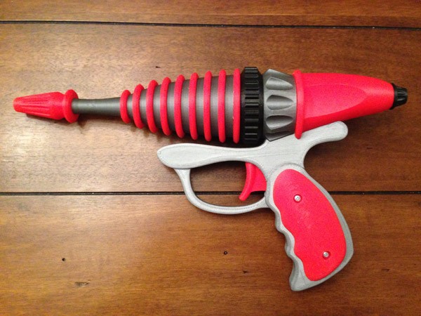
So there are 9 #4 3/8 screws, one 6″ bolt, and six sheared carriage bolts.
Prototype
When I was test-fitting and adjusting the model, I printed a version using colors I had that I don’t use much, usually accent colors and highlights, and things that I use for smaller objects. So rather than waste the real colors (which I use a lot and can’t spare as easily) I printed a fully working version (before final adjustments) in a rainbow of colors:
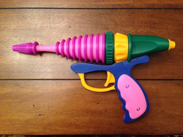
It was a throw-away, but my daughter loved it, and asked for it. So it’s now hers.
Future Plans
Electronics!
I bought some cheap carded laser guns at a dollar store, and they have very loud laser sounds and bright LEDs. I will have to do some wiring and soldering, but with a few changes, I could make this gun electronic.
Problem – The Trigger Sounds Springy
I noticed when I completed the first print that the trigger makes an ugly springy noise like rusty bed springs. I looked at the design again to see if there was anything I could do about it.
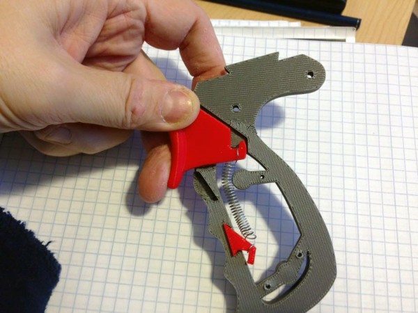
You can see the problem. The handle frame has a post for the grips to screw into. It sits amid the handle right where the spring has to be when the trigger is pulled back. The trigger is basically a lever (with the fulcrum right under my thumb.) The end of the lever inside the gun has to hold the spring, which needs an anchor somewhere else inside the frame. There’s lots of room below it, but not when the post is in the way.
The result is that when you pull the trigger, the spring is raked over that post, making a squeaky noise.
So I tried to figure out a way to remove the spring.
In the past I have made a few things that use magnets as springs:
Space 1999 Stun Gun Settings Switch
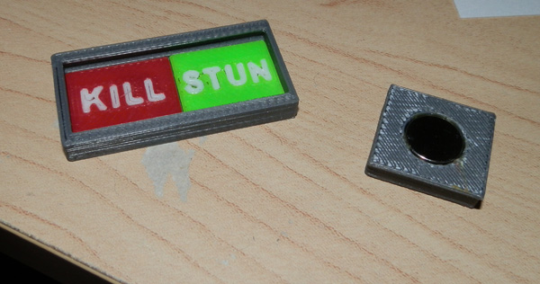
I used three magnets: One in the trigger switch slider (on the right) and there are two under the KILL and STUN settings.
EMP Grenade Plunger
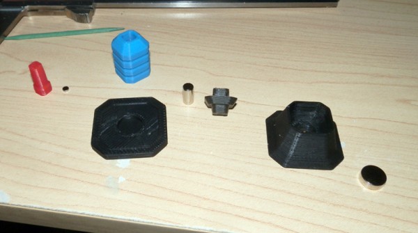
I used three magnets, one in the plunger, one in the bottom, and one in the base.
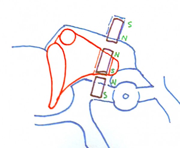
So I began to think magnets would be the perfect solution to this problem. I diagrammed out how this would fit into the existing structure. I had to make a few small changes and additions, as well as cut out some gaps for the magnets to fit, but here’s the scheme:
The trigger itself has one magnet, North pole facing upwards.
The handle has a magnet below it to pull the trigger forward. This is also North pole facing upwards for attraction
Then above the trigger a third magnet, South pole up so the two North Poles repel each other as the trigger approaches, for some resistance on the back pull.
A quick test print (in blue and brown) later and here it is:
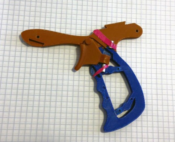
(Ugly pink tape holding the magnets in place because what really holds them in place is the two halves of the frame screwed together.)
The resulting feel is very nice. No noise, good pull resistance, and retraction.
I love it! I’ve been trying to print a new barrel for a classic 59s ray gun for an FB friend since I got my printer and failed. Full-sized ray guns are my white whale.
Well I hope you keep trying. I had a great deal of fun with this one, and will very likely make more of these in the future.
Hey there! I just wanted to ask are you on fb?
Who isn’t? :-)
Pingback: John Wick Pistol Compensator | Huxter's Words