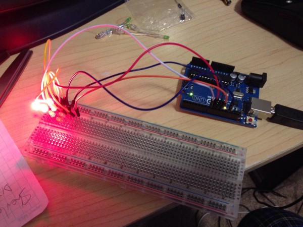
As a simple project, I decided this morning to tackle the six sided die project. That is a simple random number generator that displays its result on a six-sided die.
This picture shows the LEDs lit up to represent 5, but the lights are so bright in the pic it’s hard to distinguish.
A six sided die has seven possible pip positions, and an LED can represent each. Lit, it represents a pip, unlit it represents a space.
One might think the simple solution would be to control 7 LEDs individually, so that when you roll a 1, you turn on the center pip. Roll a two, turn on one in a corner and one in the opposite corner, individually, and so on.
However, when you think about how dice are marked, you really only need four output controls:
Because:
So any combination from 1 to 6 can be represented with just four states.
That means you only need four output pins on the Arduino. One is hooked up to just one LED, but the other three turn on TWO LEDs at the same time.
The rest is all in how you place the LEDs in space. I will 3D print a plate that puts the LEDs in the right places, and then solder the wires to control them appropriately.
The sketch, as Arduino code is called, follows:
It’s fairly straightforward. I assign numbers to variables for PinA, PinB, PinC, PinD (in case I should want to change those output pins quickly without having to change a bunch of code). Then I need a random seed, which generates pseudo random numbers each time random(x) is called. That seed creates a fixed sequence of seemingly random numbers. But with a constant seed, it will always pick the same random numbers in sequence. So I use an analogRead on a pin that has nothing attached to create the seed. This creates a more random sequence because the seed is different each time.
Then I tell the four pins I’m using to be OUTPUT pins. Serial.* allows me to write standard text output to a monitor so I can see what’s going on in there.
Then I simply pick a random number between 1 and 6 and then use that number to tell which pins to turn on (HIGH) and which to turn off (LOW).
int PinA = 8;
int PinB = 9;
int PinC = 10;
int PinD = 11;
float seed;
int Number;
int Display; // the variable needed to run my display function
void setup() {
// put your setup code here, to run once:
pinMode (PinA, OUTPUT);
pinMode (PinB, OUTPUT);
pinMode (PinC, OUTPUT);
pinMode (PinD, OUTPUT);
seed = analogRead(0); // get a fairly random value from an unconnected analog pin
randomSeed (seed); // initiate a random seed
Serial.begin(9600); // Prepare to write to the monitor
Serial.print(“\nRandom seed – “);
Serial.print(seed); // write the seed to the monitor so I can see if it’s fairly random
}
void loop() {
// put your main code here, to run repeatedly:
Number = random (6);
Number = Number + 1;
Serial.print(“\nRandom number – “);
Serial.print(Number);
// HERE INSERT CODE TO LOOP 20 TIMES, with A*time delay (so each delay is longer) calling random, then DICE(Number)
// This gives the impression the die is rolling random values until it stops picking the last one.
Dice(Number);
if (analogRead(0) < 100000){
delay (1000000);
}
}
void Dice(int myNumber) { // function to display the Number using LEDs
Serial.print(“\nNumber passed to function – “);
Serial.print(myNumber);
// reset pins – turn off all LEDs first
digitalWrite(PinA, LOW);
digitalWrite(PinB, LOW);
digitalWrite(PinC, LOW);
digitalWrite(PinD, LOW);
// Now turn them on based on myNumber
switch (myNumber){
case 1: {
Serial.print(“\nSwitching on 1”);
digitalWrite(PinA, HIGH);
digitalWrite(PinB, LOW);
digitalWrite(PinC, LOW);
digitalWrite(PinD, LOW);
return;
}
case 2: {
Serial.print(“\nSwitching on 2”);
digitalWrite(PinA, LOW);
digitalWrite(PinB, HIGH);
digitalWrite(PinC, LOW);
digitalWrite(PinD, LOW);
return;
}
case 3: {
Serial.print(“\nSwitching on 3”);
digitalWrite(PinA, HIGH);
digitalWrite(PinB, HIGH);
digitalWrite(PinC, LOW);
digitalWrite(PinD, LOW);
return;
}
case 4: {
Serial.print(“\nSwitching on 4”);
digitalWrite(PinA, LOW);
digitalWrite(PinB, HIGH);
digitalWrite(PinC, HIGH);
digitalWrite(PinD, LOW);
return;
}
case 5: {
Serial.print(“\nSwitching on 5”);
digitalWrite(PinA, HIGH);
digitalWrite(PinB, HIGH);
digitalWrite(PinC, HIGH);
digitalWrite(PinD, LOW);
return;
}
case 6: {
Serial.print(“\nSwitching on 6”);
digitalWrite(PinA, LOW);
digitalWrite(PinB, HIGH);
digitalWrite(PinC, HIGH);
digitalWrite(PinD, HIGH);
return;
}
}
}
UPDATE: 2/27/2015
Obviously it wasn’t enough to just have the Arduino choose a random number and then go into an infinite loop so that resetting the Arduino would be the only way to choose another random number (or roll the die). Resetting the Arduino can take a few seconds.
So I coded in a loop that checks for a switch. The goal was that while the switch was on, random numbers would just keep rolling until you let go the switch, then the die would roll 20 more times, slowing down each time until it finally landed on the final random number. That would be the completed roll of the die.
I spent a lot of time playing with various input devices including a SPST push-button switch pressed into the breadboard, connected to an analog input. Weirdly, as I went to push the button, the die began rolling even before my finger got to the button. I pulled it away and the die rolled down to the final number. Approach again, and it would roll.
It seemed I had invented a proximity switch from a simple push-botton on/off switch.
Turns out the Ardunio’s analog inputs can sense static charge in the immediate area, and as my finger approached the switch, the analog input began to jitter, and my code detected that as ON and went for it.
I then hooked that switch up to a variably-lit LED and saw that as my finger approached, the LED would begin to brighten. When I was touching the switch it was the brightest.
Weird.
Anyway, I played with potentiometers, pressure switches, slide switches but found that when I moved the simple push-botton to a second breadboard, it acted more like an actual on/off switch.
Then my die rolled while the switch was pressed, until I let go, then it rolled down, slowing, to the final number.
But I noticed that, naturally, sometimes the same roll would appear on the die when rolling down. I didn’t want that to show up twice, since it would look like the die was stuttering. So I added code to check the current roll against the previous roll, and if they were the same, to skip displaying it. So now it may CHOOSE two of the same random numbers while rolling, it will just give the illusion that it did not. And since it’s all for show except for the last number, this does not decrease the randomness of the roll.
Later I hooked up a small speaker to an PWM (Pulse Width Modulated) output, and output the randomly-rolled number multiplied by some factor, and as each number is displayed, it beeps during the display at a tone that corresponds to that number.
So it makes really cool beeping noise now while rolling, and the slowing roll-down sounds awesome, as the audio really sells the slowing of the die roll.
Man, now I have to move this all over to the Arduino Micro (because I want to make a housing for this die on my 3D printer).
This presents a few challenges: Powering the Micro means making a battery connect to a USB Micro jack (which is what powers the Arduino Micro) and I also need to get a light-detector working, because I’m going to be swapping out the push-button switch with a light detecting resistor on the bottom of the housing. That way, whenever you pick it up, it will roll, until you put it down, then it will roll down to the final number.
Which I think is perfect.


