Don’t Go To Jail!

At my company, several times a year they host a Game Jam. Teams are given a week to come up with a game for judging. Since we use Unity, usually the teams write a game in Unity and have a bit of fun coming up with some cute little games.

This week we are holding one with the theme: “Don’t Go To Jail!”.

I usually don’t partake, as I’m usually way too busy doing my own thing, but this year my colleague Dan Parke asked me to consider helping him with a game idea, and I agreed to at least listen.

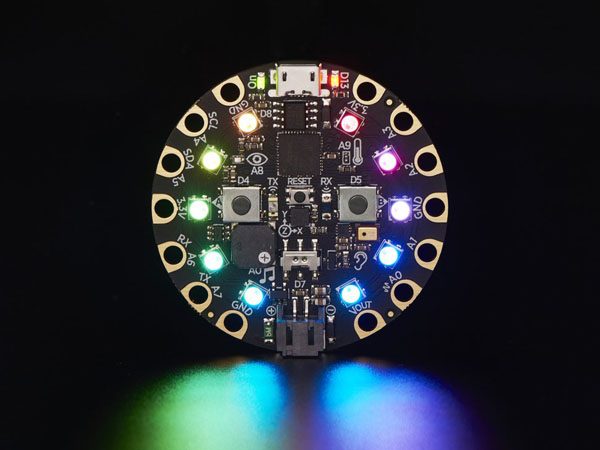
He pitched me an idea I was fascinated with right away. It was a physical game, not a computer game (as such) featuring hand movement in a game using a light sensor. The idea was to use your hand to manipulate a light on a project circuit board called Circuit Playground Express, holding it in one space for as long as you could. If you failed, you would “Go To Jail”, exactly the thing you’re supposed to avoid in this competition.

Dan thought a circuit board alone would not be very enjoyable, and was hoping I could 3D print something fun to house it in.

I was intrigued, and immediately came up with some sketched ideas for a casing for the game.

My first thought was, since I had made so many UFOs and other designs using Vending Machine bubbles, that the circuit board would perfectly fit under one, which would give us a nice first idea for a casing.

But with just the circuit board and a battery case to worry about, the casing could be quite small. But I thought since the theme was about jail, and the game idea was escaping arrest, that we needed to put this into a cartoon-like prisoner character.

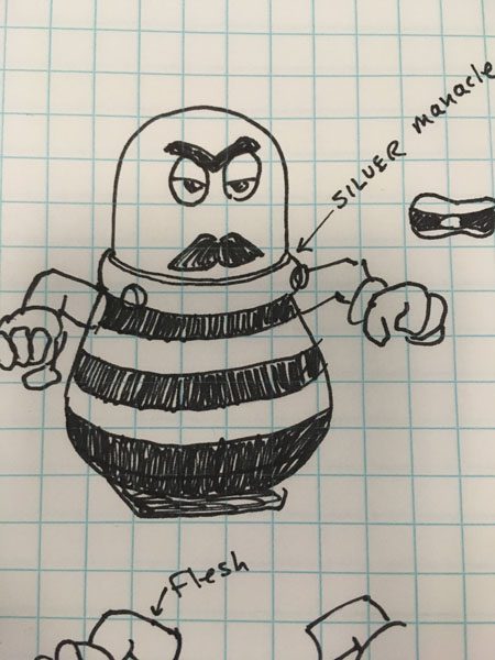
My first sketch showed an angry moustachio’d villain, which I thought a bit too angry.

My second sketch was more emotive, a bit scared, hands up, perhaps in surrender.

And since we had exactly one week to create this game from the start, I knew I could call on existing creations to make this little guy work.

The hands and arms are almost unaltered from my WERBLZ characters:

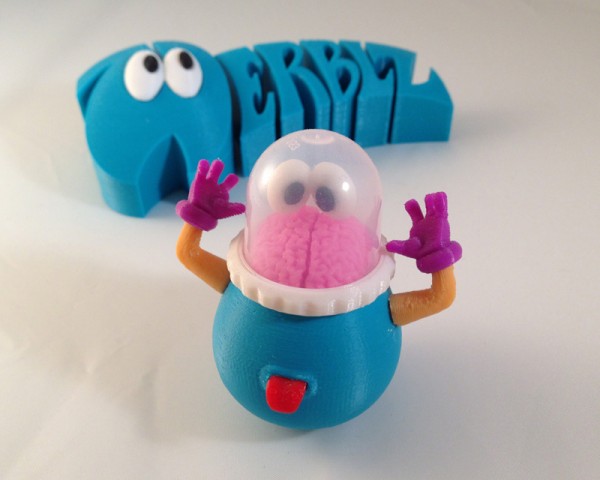
And with that, I began modeling, and soon had this basic character modeled:

Prisoner 0110 was born.

The Circuit Playground Express has touch capacitance on some of the contact points around the periphery, and that came in very handy. I was worried, though, that the capacitance would not conduct through a metal screw or other metal bit, and touching the circuit board itself would be impractical as game play. So I immediately came up with the idea of using two cotter pins I had in my own inventory already, and used a Dremel to cut them down to size, and angle the ends so they could slip over the circuit board’s contacts.

With this plan, I began immediately to model a body and a collar (a manacle) that would allow me to use these two cotter pins to secure the collar to the body and act as the function buttons of the game. Dan programmed the pins to accept touch control, and I modeled (and re-modeled, and re-modeled) a collar that would fit the circuit board and hold down well with the cotter pins.

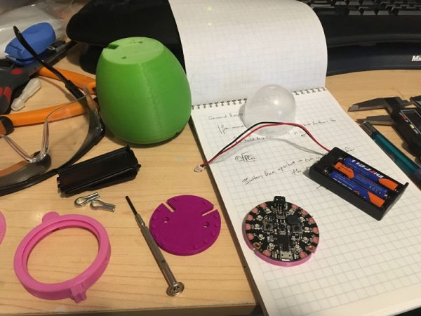
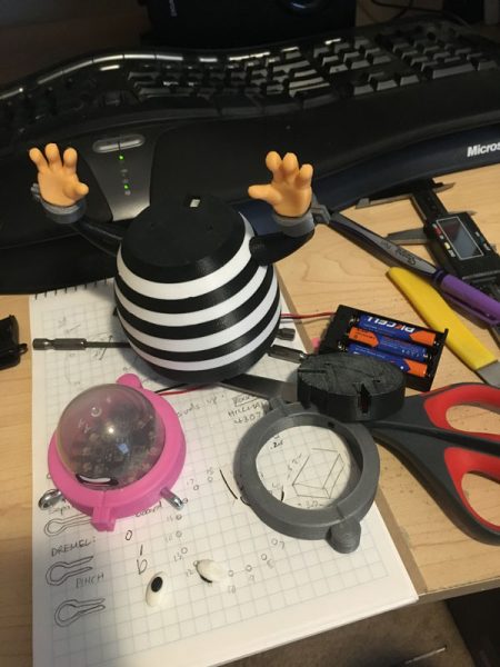
Here you see the prototype body in green, the collar base in pink (and an earlier prototype in purple) and the collar cap also in pink. (I use these colors for test prints because I don’t use them much for real, and this is better than wasting colors I have to buy a lot.)

After I assembled this all and got it working, I began detail modeling which involved slicing the body into stripes (for a prison uniform) and adding the other details. Starting with a base that could fit the battery container, and feed the wire up to the head, with room in the body for the extra length of wire.

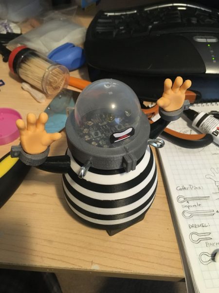
I drew a sticker for the mouth, and 3D printed eyes, manacles for the wrists, and slots for the arms. Assembly began.

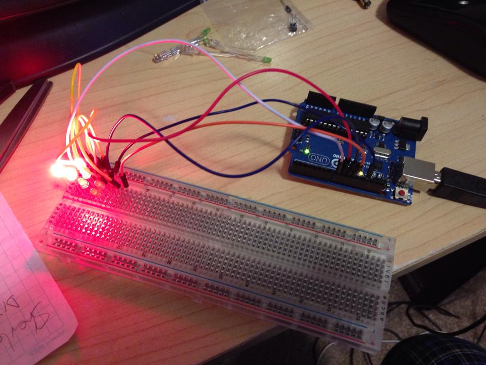
Here he is on my office desk, being tested before we began real iteration on the game itself:

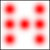
Meanwhile we did some play testing and found that the game was not quite what it could be. Dan worked on it some more and came up with the idea of having to use your hand to move a single light around the rim of the board (there are 10 lights around the circumference) and then a single light would light up, which would soon add another light to the right or left of itself, then another, in an ever-increasing arc that would come at your light “character” on either side, and your job was to hold your hand in such a way as to not let your light collide with the encroaching lights.

After that was working, complete with sound samples to tell players what to do, the game was more or less complete, and even kept track of high scores.

With a few suggestions from me during game testing, I thought flashing all lights green 3 times would be a great way to indicate you won the level, and failure should result in 3 flashes of red. I thought that would be intuitive to players.

And Dan’s original chase lights were purple. I thought the universal color for police would be more immediately recognizable, so he changed those to blue.

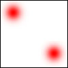
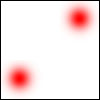
Now you are represented by a green light, which you can play with before you begin the actual game. Then you’re on your own. You can move the light around the perimeter until the cops start homing in on you. Then you have to hold your hand steady to keep the prisoner where he is. IF you can hold out with the police lights to both your left and right and not move it into them for a given interval, you win the level. If you collide with their lights for too long, you lose the game and go back to jail.

This is the final version as will be played by our judges:

The left cotter pin triggers the game to Start, while the right one can recall the high score.

Game Jam ends exactly as I’m typing this, and judging has begun. Two judges already told me they really liked the game.

3D PRINTED ZOETROPE – My Grand Project

What Is A 3D Printed Zoetrope?

Here’s one I found on YouTube that I like:

Ever since I saw my first 3D printed Zoetrope (a spinning disk with 3D printed figures on it, spun to a synchronized light which simulates a smooth animation) I set out plans to make one myself

The basis is easy – 3D print a group of figures, each frozen in a single frame of a looping animation, stuck to a spinning wheel and a strobe light set to synchronize to the rotation until you see a perfect animation.

However, there are complications, the largest being how to synchronize the light so it always aligns to the figures on the disk at an exact angle. You can spin it at a variable rate with a potentiometer on the motor and then use a variable strobe and hand-sync the two until they work, or fall out of sync due to variations in current, etc… but what I really wanted is an absolute sync, and I think I figured out a good method:


The Arduino

ArduinoMicroFront_450px

I intend to use an Arduino Micro to synchronize the light to the spinning disk. This should be easy, but some experimentation has to happen first.

First, I purchased several infra-red light emitter/detector pairs. These are LEDs, one of which emits an infra-red light, and the other detects that light. Using the pair, I should be able to trigger a circuit whenever the light is detected (or not detected) by the detector.

There are numerous examples of how to do this on the web, but it’s fairly easy. Simply hook up the emitter to an Arduino output (with an appropriate resistor to ramp down the voltage so as not to blow the LED) and the detector to an Arduino input.

Next, I will write a simple piece of Arduino code that registers the input strength (the detector is analog, so it can detect any amount of light the emitter emits.) I will use that with a variable threshold to trigger another output that I have hooked up to a very bright LED light (and perhaps even to the switch of a third-party LED flashlight).

This way I can light the LED whenever the detector sees the emitted Infrared light.

I can trigger the light to turn on and stay on only for a very short time.


Synchronization

To synchronize, I intend to print a small hole (or tab) near each 3D printed figure “frame” and then, no matter how fast I spin the disk, it will itself trigger the Emitter/Detector to flash the LED flashlight. So I should be able to spin an unmotored disk and have it sync, and as it naturally slows down, the sync will remain solid.

But of course I will use a motor to keep it going, and hopefully a motor which speed I can adjust, so I can speed up and slow down the animation.


Arduino Six Sided Die

As a simple project, I decided this morning to tackle the six sided die project. That is a simple random number generator that displays its result on a six-sided die.

dice-breadboard-01

This picture shows the LEDs lit up to represent 5, but the lights are so bright in the pic it’s hard to distinguish.

A six sided die has seven possible pip positions, and an LED can represent each. Lit, it represents a pip, unlit it represents a space.

One might think the simple solution would be to control 7 LEDs individually, so that when you roll a 1, you turn on the center pip. Roll a two, turn on one in a corner and one in the opposite corner, individually, and so on.

dice-7

However, when you think about how dice are marked, you really only need four output controls:

dice-a dice-bdice-c  dice-d

Because:

1 = dice-a

2 = dice-b

3 = dice-a and dice-b

4 = dice-b and dice-c

5 = dice-a and dice-b and dice-c

6 = dice-b and dice-c and dice-d

So any combination from 1 to 6 can be represented with just four states.

That means you only need four output pins on the Arduino. One is hooked up to just one LED, but the other three turn on TWO LEDs at the same time.

The rest is all in how you place the LEDs in space. I will 3D print a plate that puts the LEDs in the right places, and then solder the wires to control them appropriately.

The sketch, as Arduino code is called, follows:

It’s fairly straightforward. I assign numbers to variables for PinA, PinB, PinC, PinD (in case I should want to change those output pins quickly without having to change a bunch of code). Then I need a random seed, which generates pseudo random numbers each time random(x) is called. That seed creates a fixed sequence of seemingly random numbers. But with a constant seed, it will always pick the same random numbers in sequence. So I use an analogRead on a pin that has nothing attached to create the seed. This creates a more random sequence because the seed is different each time.

Then I tell the four pins I’m using to be OUTPUT pins. Serial.* allows me to write standard text output to a monitor so I can see what’s going on in there.

Then I simply pick a random number between 1 and 6 and then use that number to tell which pins to turn on (HIGH) and which to turn off (LOW).

int PinA = 8;
int PinB = 9;
int PinC = 10;
int PinD = 11;
float seed;
int Number;
int Display; // the variable needed to run my display function

void setup() {
// put your setup code here, to run once:

pinMode (PinA, OUTPUT);
pinMode (PinB, OUTPUT);
pinMode (PinC, OUTPUT);
pinMode (PinD, OUTPUT);

seed = analogRead(0); // get a fairly random value from an unconnected analog pin

randomSeed (seed); // initiate a random seed

Serial.begin(9600); // Prepare to write to the monitor

Serial.print(“\nRandom seed – “);
Serial.print(seed); // write the seed to the monitor so I can see if it’s fairly random

}

void loop() {
// put your main code here, to run repeatedly:

Number = random (6);
Number = Number + 1;
Serial.print(“\nRandom number – “);
Serial.print(Number);

// HERE INSERT CODE TO LOOP 20 TIMES, with A*time delay (so each delay is longer) calling random, then DICE(Number)
// This gives the impression the die is rolling random values until it stops picking the last one.

Dice(Number);

if (analogRead(0) < 100000){
delay (1000000);
}

}

void Dice(int myNumber) { // function to display the Number using LEDs
Serial.print(“\nNumber passed to function – “);
Serial.print(myNumber);

// reset pins – turn off all LEDs first
digitalWrite(PinA, LOW);
digitalWrite(PinB, LOW);
digitalWrite(PinC, LOW);
digitalWrite(PinD, LOW);

// Now turn them on based on myNumber
switch (myNumber){
case 1: {
Serial.print(“\nSwitching on 1”);
digitalWrite(PinA, HIGH);
digitalWrite(PinB, LOW);
digitalWrite(PinC, LOW);
digitalWrite(PinD, LOW);
return;
}
case 2: {
Serial.print(“\nSwitching on 2”);
digitalWrite(PinA, LOW);
digitalWrite(PinB, HIGH);
digitalWrite(PinC, LOW);
digitalWrite(PinD, LOW);
return;
}
case 3: {
Serial.print(“\nSwitching on 3”);
digitalWrite(PinA, HIGH);
digitalWrite(PinB, HIGH);
digitalWrite(PinC, LOW);
digitalWrite(PinD, LOW);
return;
}
case 4: {
Serial.print(“\nSwitching on 4”);
digitalWrite(PinA, LOW);
digitalWrite(PinB, HIGH);
digitalWrite(PinC, HIGH);
digitalWrite(PinD, LOW);
return;
}
case 5: {
Serial.print(“\nSwitching on 5”);
digitalWrite(PinA, HIGH);
digitalWrite(PinB, HIGH);
digitalWrite(PinC, HIGH);
digitalWrite(PinD, LOW);
return;
}
case 6: {
Serial.print(“\nSwitching on 6”);
digitalWrite(PinA, LOW);
digitalWrite(PinB, HIGH);
digitalWrite(PinC, HIGH);
digitalWrite(PinD, HIGH);
return;
}

}
}

UPDATE: 2/27/2015

Obviously it wasn’t enough to just have the Arduino choose a random number and then go into an infinite loop so that resetting the Arduino would be the only way to choose another random number (or roll the die). Resetting the Arduino can take a few seconds.

So I coded in a loop that checks for a switch. The goal was that while the switch was on, random numbers would just keep rolling until you let go the switch, then the die would roll 20 more times, slowing down each time until it finally landed on the final random number. That would be the completed roll of the die.

I spent a lot of time playing with various input devices including a SPST push-button switch pressed into the breadboard, connected to an analog input. Weirdly, as I went to push the button, the die began rolling even before my finger got to the button. I pulled it away and the die rolled down to the final number. Approach again, and it would roll.

It seemed I had invented a proximity switch from a simple push-botton on/off switch.

Turns out the Ardunio’s analog inputs can sense static charge in the immediate area, and as my finger approached the switch, the analog input began to jitter, and my code detected that as ON and went for it.

I then hooked that switch up to a variably-lit LED and saw that as my finger approached, the LED would begin to brighten. When I was touching the switch it was the brightest.

Weird.

Anyway, I played with potentiometers, pressure switches, slide switches but found that when I moved the simple push-botton to a second breadboard, it acted more like an actual on/off switch.

Then my die rolled while the switch was pressed, until I let go, then it rolled down, slowing, to the final number.

But I noticed that, naturally, sometimes the same roll would appear on the die when rolling down. I didn’t want that to show up twice, since it would look like the die was stuttering. So I added code to check the current roll against the previous roll, and if they were the same, to skip displaying it. So now it may CHOOSE two of the same random numbers while rolling, it will just give the illusion that it did not. And since it’s all for show except for the last number, this does not decrease the randomness of the roll.

Later I hooked up a small speaker to an PWM (Pulse Width Modulated) output, and output the randomly-rolled number multiplied by some factor, and as each number is displayed, it beeps during the display at a tone that corresponds to that number.

So it makes really cool beeping noise now while rolling, and the slowing roll-down sounds awesome, as the audio really sells the slowing of the die roll.

Man, now I have to move this all over to the Arduino Micro (because I want to make a housing for this die on my 3D printer).

This presents a few challenges: Powering the Micro means making a battery connect to a USB Micro jack (which is what powers the Arduino Micro) and I also need to get a light-detector working, because I’m going to be swapping out the push-button switch with a light detecting resistor on the bottom of the housing. That way, whenever you pick it up, it will roll, until you put it down, then it will roll down to the final number.

Which I think is perfect.

My New Arduino

ArduinoUno_R3_Front_450px

A few years ago, along about the time I was investigating 3D printing through, mainly, MAKE Magazine, I found that there was this rather fast-growing phenomenon surrounding a small electronic circuitboard called the Arduino.

I was interested, of course, and read a few articles which often showed some rather advanced projects, and I thought, “That looks cool, but that’s far too advanced for me.”

But I kept reading and watching what was happening, and when Radio Shack started selling Arduinos in cool kits with bunches of LEDs, sensors and other electronics, I figured I should investigate further – perhaps even get one.

But I didn’t really understand what was going on.

But like I was when I got my first computer, the Commodore 64, I was sure I could learn it and make some cool projects.

Recently I bought an Arduino, a Raspberry Pi (another circuitboard, but this one is a fully networked small computer, including USB ports, an HDMI port, and ran Linux) and an Arduino Micro, which is a smaller version of the Arduino.

But what exactly is an Arduino? Not much of what I read told me what I wanted to know. Most of the articles I read assume some knowledge of the Arduino.

One interesting fact: It was invented in Italy by two men and named after a bar they liked. That’s when I realized the name was familiar.

This poster has been hanging in my kitchen for nearly a decade. We bought it because it hangs in what used to be our favorite cafe in Norwood, MA. Here is that poster:

victoria-arduino-poster

So maybe it was destiny that I get bitten by the Arduino bug…

It turns out my initial understanding of the Arduino wasn’t far off – it is basically a computer on a chip that controls various input and output channels, and understands computer code. So if, for example, I want to turn an LED on whenever I push a button, I could simply wire a circuit up to a battery (which is a heck of a lot cheaper) or I could use my Arduino to wire up a switch, and whenever that switch turns on, have my code (which is fed to the Arduino through your computer connected by USB cable) turn the LED on. By hooking the switch up to an input pin, I can detect it, then when it turns on, use an output pin to turn on an LED.

My Arduino is the Uno, but I also bought a Micro, which is a very small version with most of the same functions.

ArduinoMicroFront_450px

(Shown here larger than actual size)

What it is, essentially, is a series of ports directly controllable through computer code uploaded to the board’s internal memory and run like a portable computer. Each pin hole does something useful and you can mix and match those to make rather complex projects.

It is so much more than that, though. With a potentiometer (variable resister, like a volume knob on a radio) I can read an analog signal, which converts to a number, and then I can feed that number out to an LED on an analog output pin and voila – the LED gets brighter as I turn the knob. Again, something most people could do with simple circuitry.

But because the Arduino understands computer code, I can do so much more. I can, if I want, use that potentiometer, and have an LED readout give the NUMBER the potentiometer is reading, through an LED display, or a row of LEDs like a bar graph – whatever my computer code can tell the output pins to do.

Suddenly the possibilities become exciting!

Over the last few days I have played with my Arduino just a bit, and got some interesting first findings, including how to blink or fade an LED (or multiple LEDs at different rates) using the various analog output pins. I also found several sensors that worked, like a pressure sensor (that turns on when you touch it) and others. I have so much more to learn.

But I intend to document some of that learning here.

I’ll start with my first project idea: A simple dice rolling program that displays its number in a way similar to how a 6 sided die works, with 3 LEDs down either side and a single LED in the middle.

Coming soon…