Arduino Six Sided Die

As a simple project, I decided this morning to tackle the six sided die project. That is a simple random number generator that displays its result on a six-sided die.

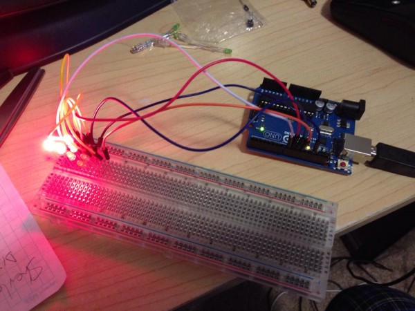
dice-breadboard-01

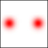
This picture shows the LEDs lit up to represent 5, but the lights are so bright in the pic it’s hard to distinguish.

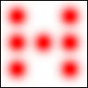
A six sided die has seven possible pip positions, and an LED can represent each. Lit, it represents a pip, unlit it represents a space.

One might think the simple solution would be to control 7 LEDs individually, so that when you roll a 1, you turn on the center pip. Roll a two, turn on one in a corner and one in the opposite corner, individually, and so on.

dice-7

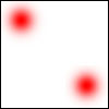
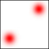
However, when you think about how dice are marked, you really only need four output controls:

dice-a dice-bdice-c  dice-d

Because:

1 = dice-a

2 = dice-b

3 = dice-a and dice-b

4 = dice-b and dice-c

5 = dice-a and dice-b and dice-c

6 = dice-b and dice-c and dice-d

So any combination from 1 to 6 can be represented with just four states.

That means you only need four output pins on the Arduino. One is hooked up to just one LED, but the other three turn on TWO LEDs at the same time.

The rest is all in how you place the LEDs in space. I will 3D print a plate that puts the LEDs in the right places, and then solder the wires to control them appropriately.

The sketch, as Arduino code is called, follows:

It’s fairly straightforward. I assign numbers to variables for PinA, PinB, PinC, PinD (in case I should want to change those output pins quickly without having to change a bunch of code). Then I need a random seed, which generates pseudo random numbers each time random(x) is called. That seed creates a fixed sequence of seemingly random numbers. But with a constant seed, it will always pick the same random numbers in sequence. So I use an analogRead on a pin that has nothing attached to create the seed. This creates a more random sequence because the seed is different each time.

Then I tell the four pins I’m using to be OUTPUT pins. Serial.* allows me to write standard text output to a monitor so I can see what’s going on in there.

Then I simply pick a random number between 1 and 6 and then use that number to tell which pins to turn on (HIGH) and which to turn off (LOW).

int PinA = 8;
int PinB = 9;
int PinC = 10;
int PinD = 11;
float seed;
int Number;
int Display; // the variable needed to run my display function

void setup() {
// put your setup code here, to run once:

pinMode (PinA, OUTPUT);
pinMode (PinB, OUTPUT);
pinMode (PinC, OUTPUT);
pinMode (PinD, OUTPUT);

seed = analogRead(0); // get a fairly random value from an unconnected analog pin

randomSeed (seed); // initiate a random seed

Serial.begin(9600); // Prepare to write to the monitor

Serial.print(“\nRandom seed – “);
Serial.print(seed); // write the seed to the monitor so I can see if it’s fairly random

}

void loop() {
// put your main code here, to run repeatedly:

Number = random (6);
Number = Number + 1;
Serial.print(“\nRandom number – “);
Serial.print(Number);

// HERE INSERT CODE TO LOOP 20 TIMES, with A*time delay (so each delay is longer) calling random, then DICE(Number)
// This gives the impression the die is rolling random values until it stops picking the last one.

Dice(Number);

if (analogRead(0) < 100000){
delay (1000000);
}

}

void Dice(int myNumber) { // function to display the Number using LEDs
Serial.print(“\nNumber passed to function – “);
Serial.print(myNumber);

// reset pins – turn off all LEDs first
digitalWrite(PinA, LOW);
digitalWrite(PinB, LOW);
digitalWrite(PinC, LOW);
digitalWrite(PinD, LOW);

// Now turn them on based on myNumber
switch (myNumber){
case 1: {
Serial.print(“\nSwitching on 1”);
digitalWrite(PinA, HIGH);
digitalWrite(PinB, LOW);
digitalWrite(PinC, LOW);
digitalWrite(PinD, LOW);
return;
}
case 2: {
Serial.print(“\nSwitching on 2”);
digitalWrite(PinA, LOW);
digitalWrite(PinB, HIGH);
digitalWrite(PinC, LOW);
digitalWrite(PinD, LOW);
return;
}
case 3: {
Serial.print(“\nSwitching on 3”);
digitalWrite(PinA, HIGH);
digitalWrite(PinB, HIGH);
digitalWrite(PinC, LOW);
digitalWrite(PinD, LOW);
return;
}
case 4: {
Serial.print(“\nSwitching on 4”);
digitalWrite(PinA, LOW);
digitalWrite(PinB, HIGH);
digitalWrite(PinC, HIGH);
digitalWrite(PinD, LOW);
return;
}
case 5: {
Serial.print(“\nSwitching on 5”);
digitalWrite(PinA, HIGH);
digitalWrite(PinB, HIGH);
digitalWrite(PinC, HIGH);
digitalWrite(PinD, LOW);
return;
}
case 6: {
Serial.print(“\nSwitching on 6”);
digitalWrite(PinA, LOW);
digitalWrite(PinB, HIGH);
digitalWrite(PinC, HIGH);
digitalWrite(PinD, HIGH);
return;
}

}
}

UPDATE: 2/27/2015

Obviously it wasn’t enough to just have the Arduino choose a random number and then go into an infinite loop so that resetting the Arduino would be the only way to choose another random number (or roll the die). Resetting the Arduino can take a few seconds.

So I coded in a loop that checks for a switch. The goal was that while the switch was on, random numbers would just keep rolling until you let go the switch, then the die would roll 20 more times, slowing down each time until it finally landed on the final random number. That would be the completed roll of the die.

I spent a lot of time playing with various input devices including a SPST push-button switch pressed into the breadboard, connected to an analog input. Weirdly, as I went to push the button, the die began rolling even before my finger got to the button. I pulled it away and the die rolled down to the final number. Approach again, and it would roll.

It seemed I had invented a proximity switch from a simple push-botton on/off switch.

Turns out the Ardunio’s analog inputs can sense static charge in the immediate area, and as my finger approached the switch, the analog input began to jitter, and my code detected that as ON and went for it.

I then hooked that switch up to a variably-lit LED and saw that as my finger approached, the LED would begin to brighten. When I was touching the switch it was the brightest.

Weird.

Anyway, I played with potentiometers, pressure switches, slide switches but found that when I moved the simple push-botton to a second breadboard, it acted more like an actual on/off switch.

Then my die rolled while the switch was pressed, until I let go, then it rolled down, slowing, to the final number.

But I noticed that, naturally, sometimes the same roll would appear on the die when rolling down. I didn’t want that to show up twice, since it would look like the die was stuttering. So I added code to check the current roll against the previous roll, and if they were the same, to skip displaying it. So now it may CHOOSE two of the same random numbers while rolling, it will just give the illusion that it did not. And since it’s all for show except for the last number, this does not decrease the randomness of the roll.

Later I hooked up a small speaker to an PWM (Pulse Width Modulated) output, and output the randomly-rolled number multiplied by some factor, and as each number is displayed, it beeps during the display at a tone that corresponds to that number.

So it makes really cool beeping noise now while rolling, and the slowing roll-down sounds awesome, as the audio really sells the slowing of the die roll.

Man, now I have to move this all over to the Arduino Micro (because I want to make a housing for this die on my 3D printer).

This presents a few challenges: Powering the Micro means making a battery connect to a USB Micro jack (which is what powers the Arduino Micro) and I also need to get a light-detector working, because I’m going to be swapping out the push-button switch with a light detecting resistor on the bottom of the housing. That way, whenever you pick it up, it will roll, until you put it down, then it will roll down to the final number.

Which I think is perfect.

My New Arduino

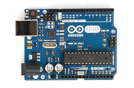
ArduinoUno_R3_Front_450px

A few years ago, along about the time I was investigating 3D printing through, mainly, MAKE Magazine, I found that there was this rather fast-growing phenomenon surrounding a small electronic circuitboard called the Arduino.

I was interested, of course, and read a few articles which often showed some rather advanced projects, and I thought, “That looks cool, but that’s far too advanced for me.”

But I kept reading and watching what was happening, and when Radio Shack started selling Arduinos in cool kits with bunches of LEDs, sensors and other electronics, I figured I should investigate further – perhaps even get one.

But I didn’t really understand what was going on.

But like I was when I got my first computer, the Commodore 64, I was sure I could learn it and make some cool projects.

Recently I bought an Arduino, a Raspberry Pi (another circuitboard, but this one is a fully networked small computer, including USB ports, an HDMI port, and ran Linux) and an Arduino Micro, which is a smaller version of the Arduino.

But what exactly is an Arduino? Not much of what I read told me what I wanted to know. Most of the articles I read assume some knowledge of the Arduino.

One interesting fact: It was invented in Italy by two men and named after a bar they liked. That’s when I realized the name was familiar.

This poster has been hanging in my kitchen for nearly a decade. We bought it because it hangs in what used to be our favorite cafe in Norwood, MA. Here is that poster:

victoria-arduino-poster

So maybe it was destiny that I get bitten by the Arduino bug…

It turns out my initial understanding of the Arduino wasn’t far off – it is basically a computer on a chip that controls various input and output channels, and understands computer code. So if, for example, I want to turn an LED on whenever I push a button, I could simply wire a circuit up to a battery (which is a heck of a lot cheaper) or I could use my Arduino to wire up a switch, and whenever that switch turns on, have my code (which is fed to the Arduino through your computer connected by USB cable) turn the LED on. By hooking the switch up to an input pin, I can detect it, then when it turns on, use an output pin to turn on an LED.

My Arduino is the Uno, but I also bought a Micro, which is a very small version with most of the same functions.

ArduinoMicroFront_450px

(Shown here larger than actual size)

What it is, essentially, is a series of ports directly controllable through computer code uploaded to the board’s internal memory and run like a portable computer. Each pin hole does something useful and you can mix and match those to make rather complex projects.

It is so much more than that, though. With a potentiometer (variable resister, like a volume knob on a radio) I can read an analog signal, which converts to a number, and then I can feed that number out to an LED on an analog output pin and voila – the LED gets brighter as I turn the knob. Again, something most people could do with simple circuitry.

But because the Arduino understands computer code, I can do so much more. I can, if I want, use that potentiometer, and have an LED readout give the NUMBER the potentiometer is reading, through an LED display, or a row of LEDs like a bar graph – whatever my computer code can tell the output pins to do.

Suddenly the possibilities become exciting!

Over the last few days I have played with my Arduino just a bit, and got some interesting first findings, including how to blink or fade an LED (or multiple LEDs at different rates) using the various analog output pins. I also found several sensors that worked, like a pressure sensor (that turns on when you touch it) and others. I have so much more to learn.

But I intend to document some of that learning here.

I’ll start with my first project idea: A simple dice rolling program that displays its number in a way similar to how a 6 sided die works, with 3 LEDs down either side and a single LED in the middle.

Coming soon…

Thunderbird 1 – Take 2

Last year it was announced that WETA, who made all of the awesome designs for the Lord of the Rings and Hobbit movies, among other accomplishments, would be reviving the iconic TV series Thunderbirds, created by Gerry and Sylvia Anderson in 1964. The new series is going to be named after the first of two feature films the couple also made back in the day: Thunderbirds Are Go.

The first big teaser image from the show is the CGI model of the updated Thunderbird 1, seen here:

tag-tb1-cgi-model-01

It was soon followed by this image, almost the same, of Thunderbird 1 (TB1) flying inverted over the Hollywood sign:

tag-tb1-cgi-model-02

So I set out to model this and 3D print it using my Afinia H479 printer. (And my Afinia H480.)

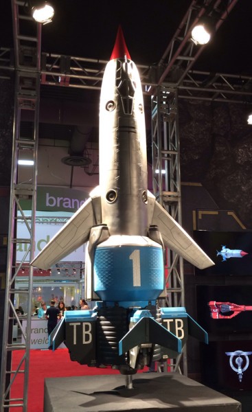
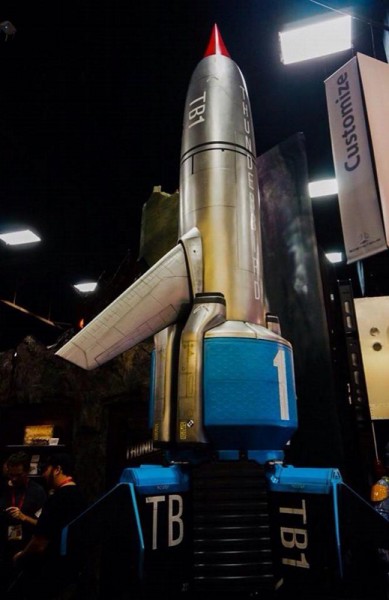
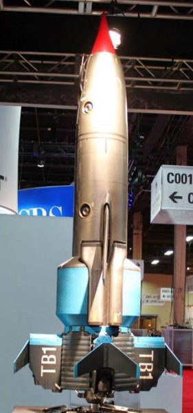
Luckily, WETA has been touring around the toy and merchandising conventions with a large 10 foot physical model of the ship too, and some photos gave me more information about shape and proportion, as well as detail.

tag-tb1-physical-model-underside tag-tb1-physical-model-02 tag-tb1-physical-model-01

And of further help, a friend of mine, Barry Kay, took some very nice high-rez close-up detail shots from various angles all around the model, which I used to work out a lot of the detail. (I may post those later.)

The Parts

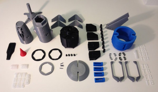
Here is a photo of all of the parts that make up this model. Note that there are 98 individual parts, including a display stand.

tag-tb1-3dprint-parts-all

The Main Body

The main body tube is made up of five separate parts. These parts comprise the main tube in silver, and two stripes in black mid-body.

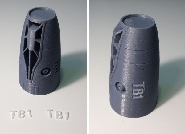
Here, the top section has two underjets, and cutouts for the cockpit windows and body text which will inlay as white pieces.

Here the side text is inlaid, so that the TB1 reads upright from either side of the body (only one side shown here.)

tag-tb1-3dprint-body-side-text-inlaid-01

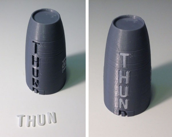
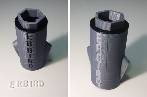
Then the topside of the body, which has the word THUNDERBIRD going down its entire length, is inserted, or at least the first few letters that are printed on this top section.

tag-tb1-3dprint-body-top-text-front-01

Then I do the same for the bottom body tube section:

tag-tb1-3dprint-body-bottom-text-01

Next I attach the five main section pieces including the sandwiched black/silver/black rings, which leaves a hole for the letter D:

tag-tb1-3dprint-body-main-assembled-missing-d

The Engine Section

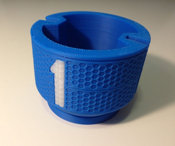
The blue section of the body, if you look closely, is honeycombed with hexagons. This was the most difficult part of this model to make, but it was oh-so-satisfying when it printed so nicely. I cut the large number 1 from it and made that an inlaid piece, but with the honeycombing intact.
tag-tb1-3dprint-body-section-1

Here is an image someone posted of a texture used on this part of the body:

tag-tb1-cgi-body-detail

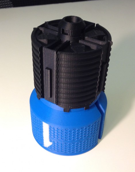
Here, I attach the large dark part, which looks like a heat sink, to the blue section. Note the detail on the bottom. This was not in any of the photos or CGI images I have seen.

tag-tb1-3dprint-body-rear-assembled

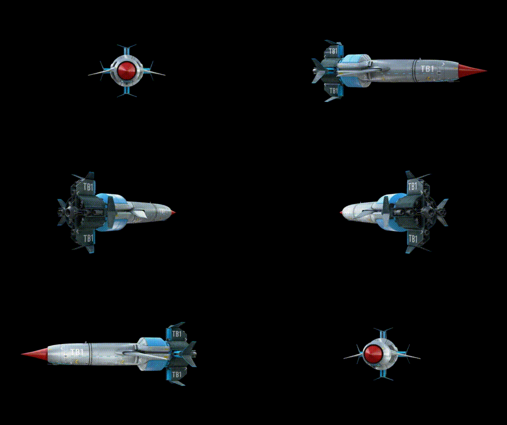
I got the detail from a rough GIF file someone posted of a turntable rendering of the ship that was on display on monitors next to the physical models at the conventions:

thunderbird-1

I snapped two frames of this GIF as it rotated and used them side-by-side to create a 3D parallax image (like a ViewMaster slide) and while the video has serious GIF dithering, I was able to make out some detail in depth, so I modeled in what I could see.

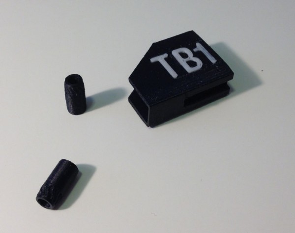
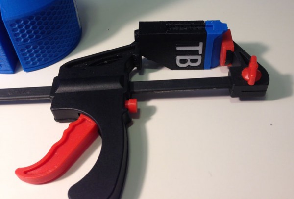
Next come the thruster housings for the 8 jet engines. Each housing has TB or TB1 (depending on which one) inlaid in, and two jet engines attached:

tag-tb1-3dprint-engine-housing-jets

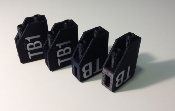
Here are the four housings:

tag-tb1-3dprint-engine-housings-done

I had a conflict here. While the rotating turntable image (posted above) clearly shows the TB1 as upright on the upper and lower housings, so when the ship is landed flat it reads correctly, the physical model my friend photographed showed the TB1 as reading upright relative to the body, so I decided to go with the physical model for now.

(To make that a changeable thing, I opted not to glue the bottom thruster housing in place. It snaps in rather well, so it holds. Later, I will reprint that one with the TB1 facing the way it faces on the CGI model.)

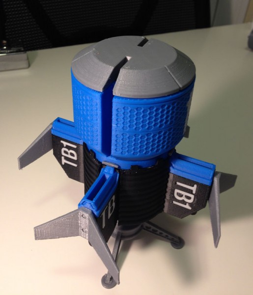
Then I added the blue jet intakes to the tops of each thruster housing:

tag-tb1-3dprint-engine-housing-intake-attached

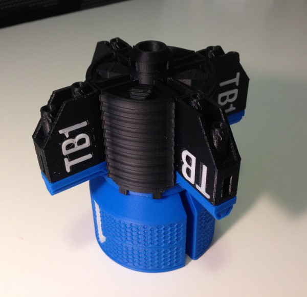
Then I added the housings to the heat sink section:

tag-tb1-3dprint-engine-housings-attached

Next I added the fins

tag-tb1-3dprint-fins-attached

Then the flare section that connects the engine section with the body section, adding the silver pins to the tops of the thruster intakes. (Note the display stand, which is not canon. I just made it interesting.)

tag-tb1-3dprint-body-bottom-assemby

I then joined the two body sections together.

tag-tb1-3dprint-mostly-done

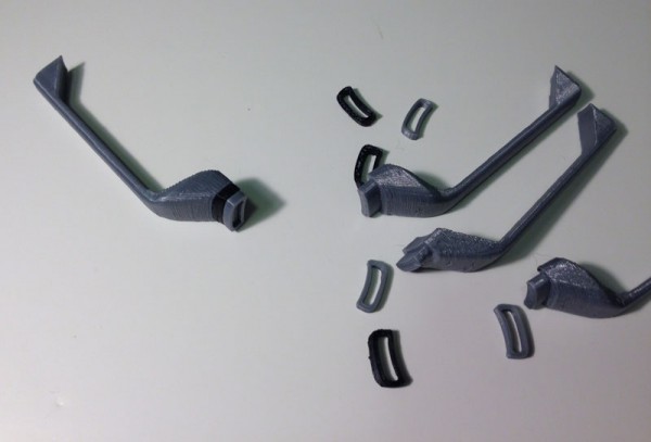
Next are the main engine intakes, each made from 3 pieces:

tag-tb1-3dprint-engine-intakes

These get attached next to the slots where the wings would retract:

tag-tb1-3dprint-engine-intakes-assembly

Last Bits

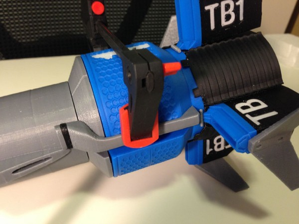
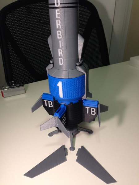
Then I prepared the wings, which have tabs that fit into slots in the body shoulders.

tag-tb1-3dprint-wings

And here they are, slotted in place.

tag-tb1-3dprint-wings-assembled

(In a future version of this model, these wings will actually scissor out on gears, so they can retract, like they do on the show. But for now this will do. The wings on this model are static. Making them do what I hope to do later will be quite a complicated job, but one I hope to take on later this year.)

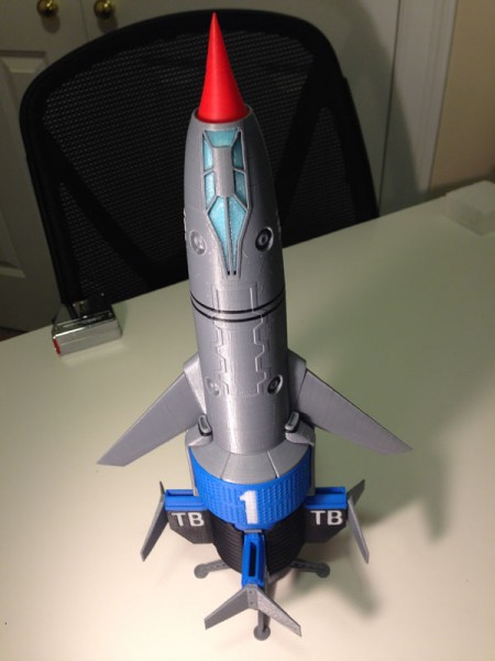
Almost the last part is the nose-cone:

tag-tb1-3dprint-fully-assembled-on-stand-topside

The very first image showing all of the parts has the window inlays printed in black. While I was assembling this model, I got a shipment with some glow-in-the-dark sky blue filament from Zen Toolworks, and I printed the windows again in that color to see if it worked better than black.

I also used a sample Zen sent me of translucent filament and tried that.

The winner was blue:

tag-tb1-3dprint-fully-assembled-on-stand-underside

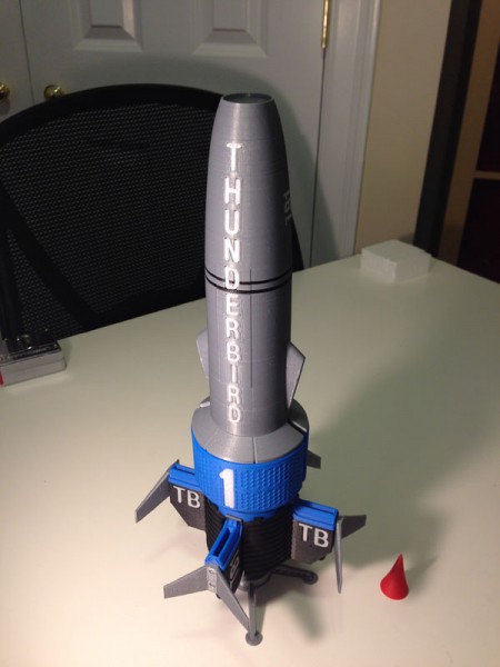
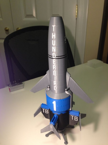
So there you have it. My version of WETA’s Thunderbird 1 from Thunderbirds Are Go.

Here it is on display:

tag-tb1-3dprint-fully-assembled-on-display-underside tag-tb1-3dprint-fully-assembled-on-display-topside

Still missing: The Pitot tube which juts from the cockpit area, and some other body detailing, which I hope to add when I make the retractable-wing version later.