Re-Introducing JANI-TOR

bjanitor

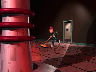
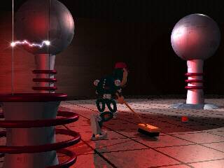
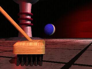
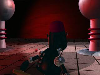
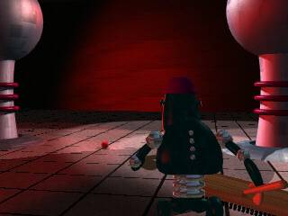
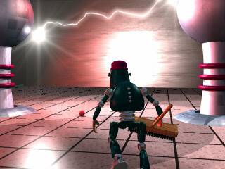
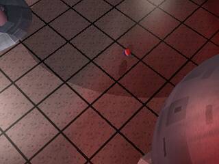
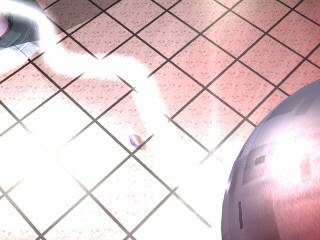
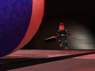
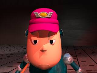
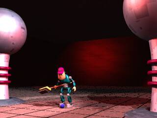
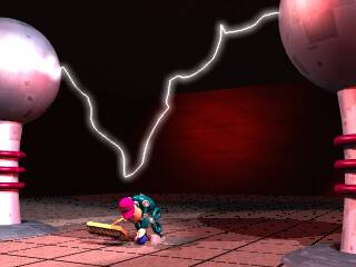
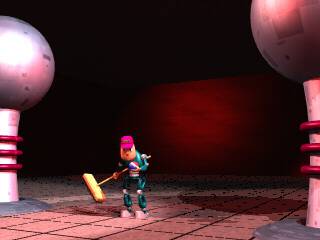
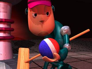
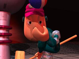
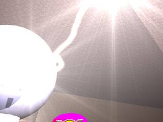
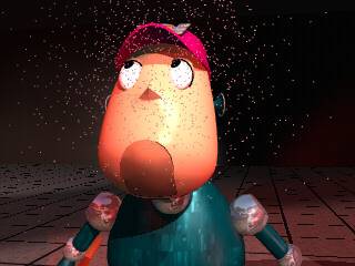
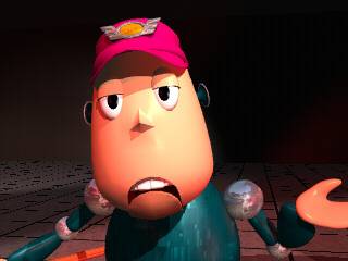
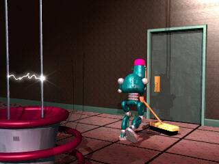
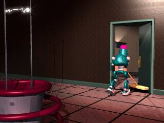
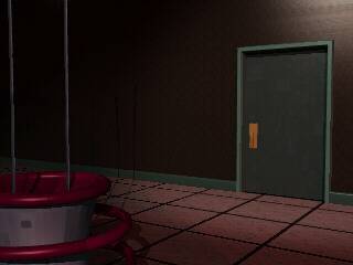
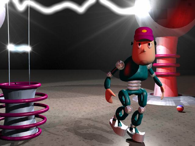
In the late 1990s I created a robot in Lightwave, and called him JANI-TOR. The idea was that he was a menial sanitation robot sweeping the floor of a lab he’s not necessarily supposed to be in. His broom bumps a ball (a familiar one to Canadian children in the 1970s, and is NOT, I repeat, NOT the PEPSI logo!) and follows the ball to where it rolls to a halt under a huge Van de Graaf generator, where he reaches down to pick it up as the sparks get increasingly closer to him, and then he stands up, the generator waning, and examines the ball, tosses it in the air where a huge spark disintegrates it, turning it into dust. Undaunted by any of this, JANI-TOR continues about his business.

I put the video together but never did the sound.

This week I decided I wanted to 3D print him. Actually, I decided this many years ago when 3D printing became possible.

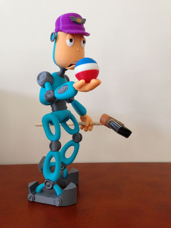
This week I remodeled him (can’t find the original Lightwave files), updated a few things, like his hands, and beefed up his feet, and printed him in his broom-carrying, ball-surveying pose.

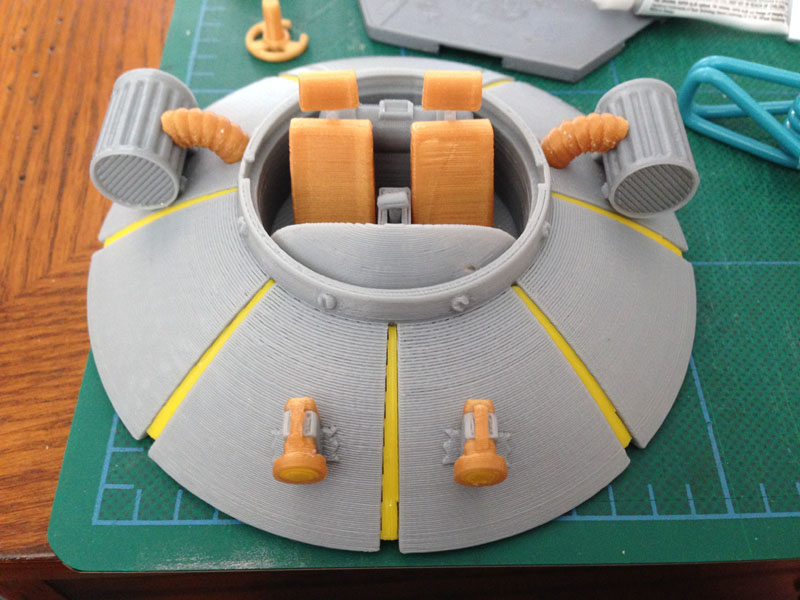
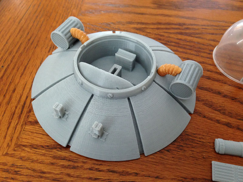
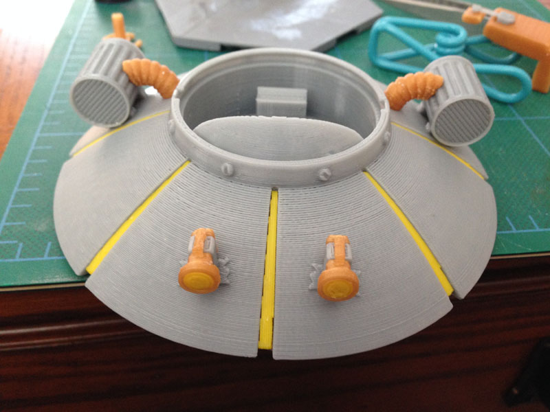
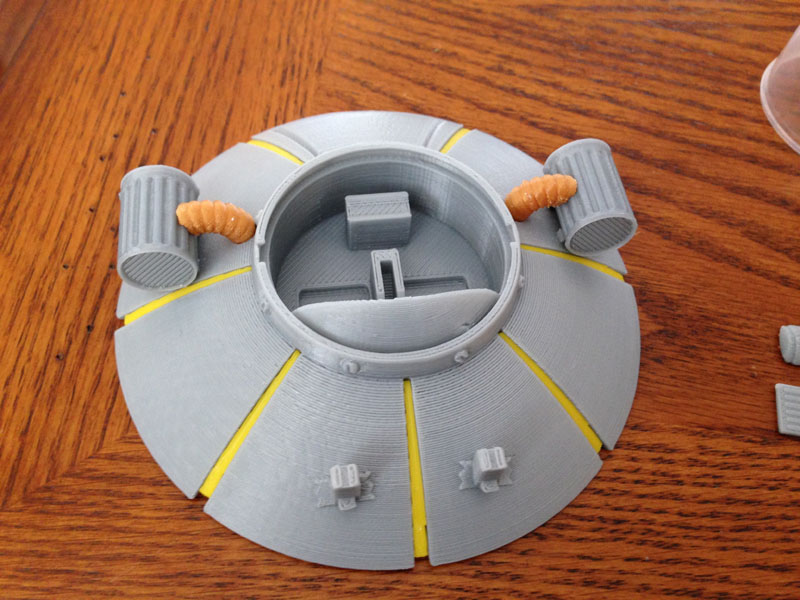
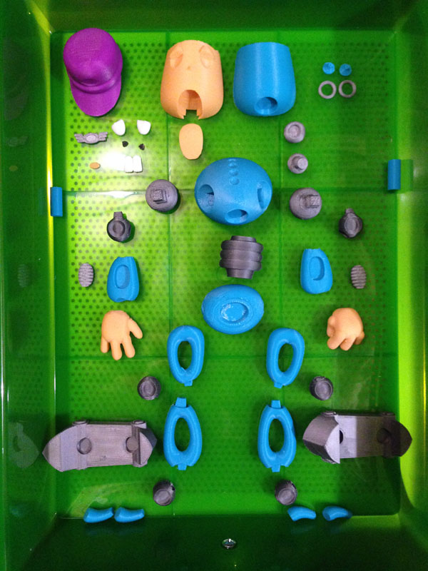
Here is a tray filled with all of the parts: The dark teal of the original was not available, so I used a lighter version, and I still think he turned out well:

jani-tor-parts-01

And here he is, printed out. As you can see by the parts, it’s all tab and slot connections, and so he’s not articulated. He’s a statue. But a nice one.

jani-tor-01 jani-tor-02

jani-tor-03

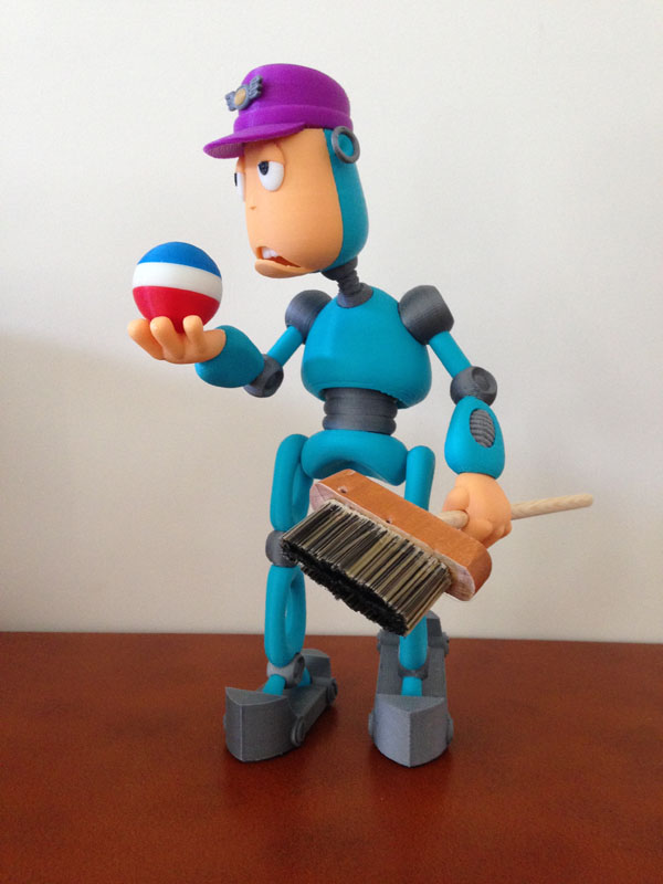
I posed his eyes looking a bit too high. I can fix that by printing a new head for a different version.

Note the broom. I could have 3D printed that too, but guess what? Sometimes 3D printing is not the only, and not necessarily ideal, method to make something. This time I used two paint brushes (one for the wooden base, and one for the bristles) and a piece of wooden dowel. The hand has a cylindrical space in it so the broom can slide into place easily.

Here are the movies, one is a walk test, and the other the full video. These are tiny because it was the late 1990s and this size took long enough to render. It was also a test only.

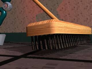
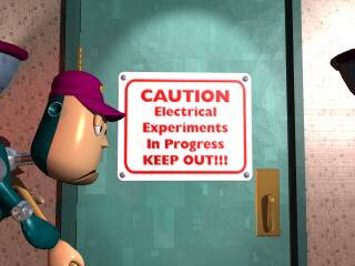
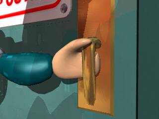
Here is a series of single frames from the animation. Each one mimics the storyboard frame I created for them very closely. I stuck to my storyboard fairly strictly.

shota shotb shotc shote shotf shotg shoti1 shoti2 shoti3 shoth1 shoth2 shotj shotk shotl1 shotl2 shotl3 shotm1 shotm2shotm3 shotn1  shotn2 shoto1 shoto2 shoto3


Rick & Morty – Flying Saucer Car – Talk about Iterative Design

IMG_4093

I am involved in many projects, both at home and at work. Each one has shown me how important iterative development is. I have found that nothing is ever “done” but it does get ever-closer-to-done.

At the request of a friend I took on the fun task of modeling and 3D printing Rick’s flying saucer car from Rick & Morty, the Adult Swim cartoon series.  This request was probably prompted because I had been creating things using vending machine bubble capsules, and the ship has a perfect bubble-capsule canopy. (This is a good series, but it is not for kids.)

I found first that no matter how much research I do on the web, I see no two versions of the ship are alike, which is expected because they are hand drawn by various artists.

I did a quick version that worked fairly well:

rm-test-print-01

But of course this was a test print only. I had full plans to do a detailed interior.

The problem: I made the aperture for the capsule tight. Very tight. Applying the capsule should be done only once, and it could be tight. To get it to fit, I had to warp the edge inward, snap most of it in, then let it relax outward to fit the rest of the circular indentation.

So that worked. Then I added the detailed cockpit interior. When I was done, I had 50 individual pieces to make the car with the detail I wanted. (Some of this was to make printing easier or cleaner, such as making the interior tank out of 3 pieces instead of 1.)

rm-full1-04 rm-full1-03 rm-full1-02 rm-full1-01

Uh-oh. I soon found that there was no room to bend the capsule inward to fit it properly without dislodging or breaking items inside the cockpit.

I had to think for a bit. This version is solid. Can’t fix it. So perhaps I can try to get it to fit after all, but it will be hard.

But then I came up with the perfect idea:

I would break the interior out as a circular floor, and cut it out of the body, and then install it from below after the bubble capsule is in place. The bottom would glue to the body, and then the oval under-piece will cover the hole. The result will be visually identical, but far easier to assemble.

UPDATE: Nov 23, 2015 – The Finished Ship

Here is a photo of the finished ship. I also created and added waterslide decals of the “bumper stickers” on the side of the ship.

rm-ship-finished-decals-01

This version has the separate cockpit which allows for easier assembly.

Sooooo… interesting story:

This whole project was suggested to me by my friend Bil Mauritzen. When I sent him a copy, he showed photos of it to the co-creator of “Rick & Morty”, Justin Roiland who reportedly said it was the best bleeping thing he’d seen.

I sent a second one to Bil, who will be giving it to Justin.

So that happened.


3D PRINTED ZOETROPE – My Grand Project

What Is A 3D Printed Zoetrope?

Here’s one I found on YouTube that I like:

Ever since I saw my first 3D printed Zoetrope (a spinning disk with 3D printed figures on it, spun to a synchronized light which simulates a smooth animation) I set out plans to make one myself

The basis is easy – 3D print a group of figures, each frozen in a single frame of a looping animation, stuck to a spinning wheel and a strobe light set to synchronize to the rotation until you see a perfect animation.

However, there are complications, the largest being how to synchronize the light so it always aligns to the figures on the disk at an exact angle. You can spin it at a variable rate with a potentiometer on the motor and then use a variable strobe and hand-sync the two until they work, or fall out of sync due to variations in current, etc… but what I really wanted is an absolute sync, and I think I figured out a good method:


The Arduino

ArduinoMicroFront_450px

I intend to use an Arduino Micro to synchronize the light to the spinning disk. This should be easy, but some experimentation has to happen first.

First, I purchased several infra-red light emitter/detector pairs. These are LEDs, one of which emits an infra-red light, and the other detects that light. Using the pair, I should be able to trigger a circuit whenever the light is detected (or not detected) by the detector.

There are numerous examples of how to do this on the web, but it’s fairly easy. Simply hook up the emitter to an Arduino output (with an appropriate resistor to ramp down the voltage so as not to blow the LED) and the detector to an Arduino input.

Next, I will write a simple piece of Arduino code that registers the input strength (the detector is analog, so it can detect any amount of light the emitter emits.) I will use that with a variable threshold to trigger another output that I have hooked up to a very bright LED light (and perhaps even to the switch of a third-party LED flashlight).

This way I can light the LED whenever the detector sees the emitted Infrared light.

I can trigger the light to turn on and stay on only for a very short time.


Synchronization

To synchronize, I intend to print a small hole (or tab) near each 3D printed figure “frame” and then, no matter how fast I spin the disk, it will itself trigger the Emitter/Detector to flash the LED flashlight. So I should be able to spin an unmotored disk and have it sync, and as it naturally slows down, the sync will remain solid.

But of course I will use a motor to keep it going, and hopefully a motor which speed I can adjust, so I can speed up and slow down the animation.