MPC / fundimensions Revised Moonbase Alpha Model Kit

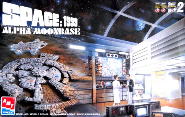
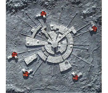
How I envied my friend back in the 1970s when he got the model kit of Moonbase Alpha from the TV series Space:1999. It featured a moon diorama base with the radial iconic Moonase Alpha, with three Eagle Launch Pads, six miniature Eagles and as a bonus, a larger model of the Main Mission room complete with tiny figures.

moonase-alpha-original-kit-box-cover

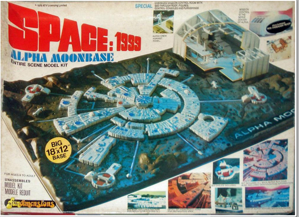
Some years ago, AMT/ERTL reproduced the kit, fairly accurately, but notoriously with a vacuum-formed base that was not very good. The tubes leading out to the launch pads were molded into the base and badly defined, and the launch pads themselves had issues: they were too large (by 20%) and there were only 3 of them when there should be 5. This meant that the tubes were incomplete, since the pads needed to be connected to base by transport tubes.

moonbase-alpha-ertl-repro-kit-cover

Nonetheless I snapped up a copy of that repro kit for later construction.

I decided the base itself was not going to cut it, and what I ultimately wanted to do was make a square, framed wall hanging of this moonbase to hang on my wall.

Last year I took it upon myself to take the moonbase parts (the base itself is not bad) and make my own lunar landscape, lay down the moonbase, then use coat hanger wire (the only thing I could find to scale – but heavy) and 3D print smaller launch pads, and lay out a very accurate Moonbase Alpha.

layout-to-scale-I-hope

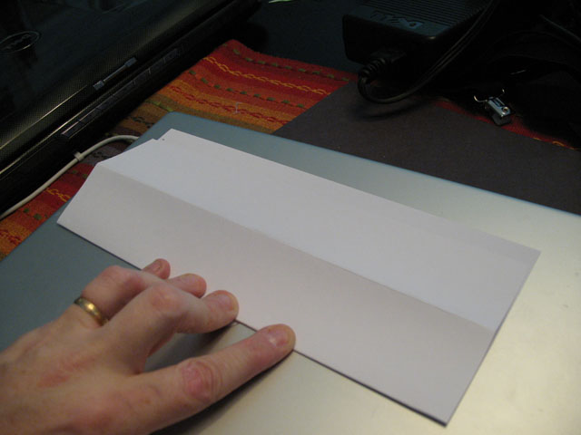
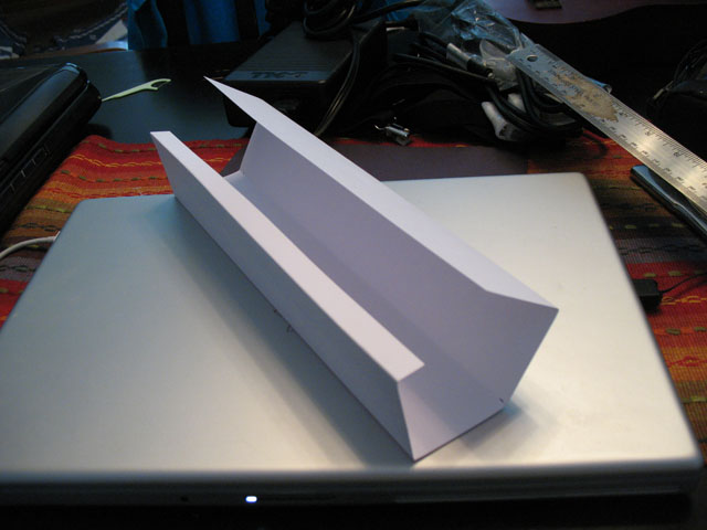
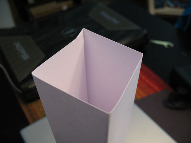
I cut a 50cm x 50cm piece of styrofoam pink insulation sheeting (a go-to favorite for project work) and spray-painted it. Spray-paint eats away at styrofoam, so the result was a rough lunar landscape with craters and mountains carefully sprayed in. Then I used craft paint with a roller to paint it and cover the pink pock-marks I made with the spraypaint.

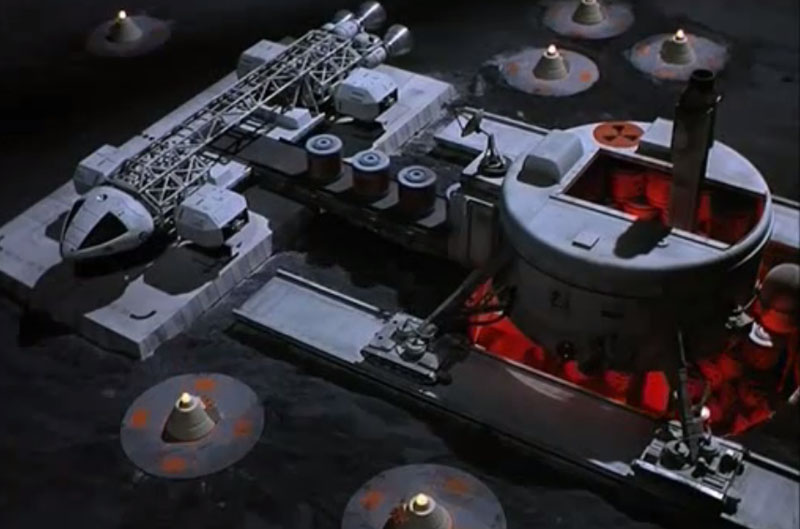
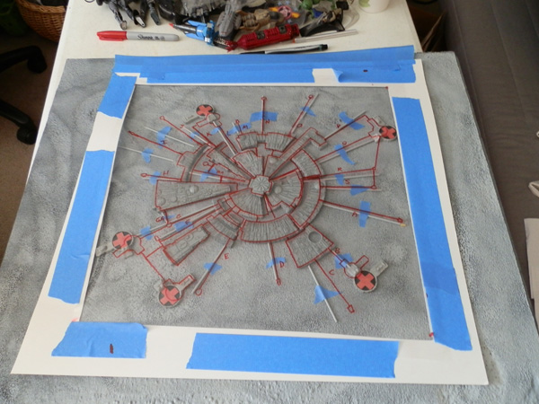
Here is the rough layout before I put the transport tubes in place:

OLYMPUS DIGITAL CAMERA

The Alpha Moonbase patch was to be part of the display.

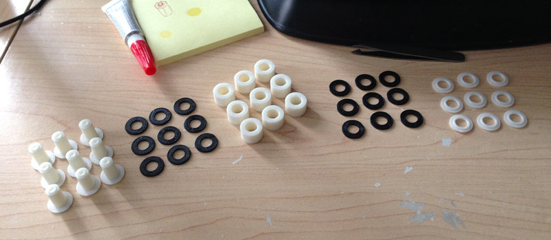
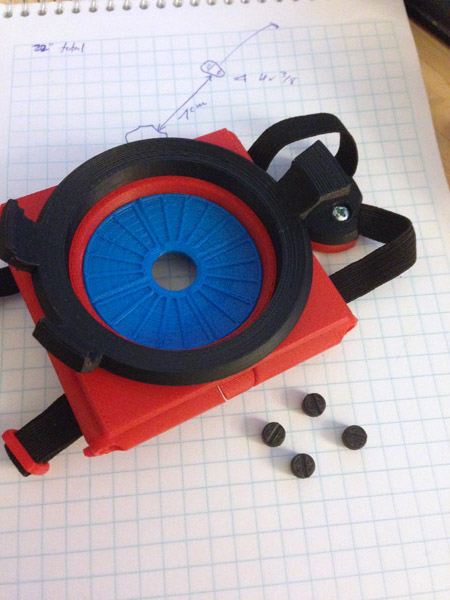
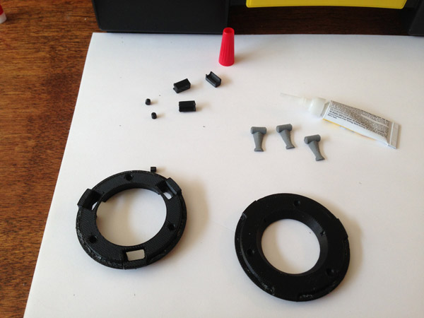
I began this project before I got a 3D printer, so the first thing I had to do was create two more launch pads or buy them. I bought some molding putty and epoxy resin and molded and cast a few pads:

OLYMPUS DIGITAL CAMERA

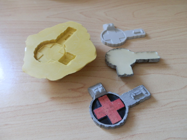
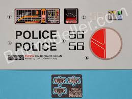
I printed the landing crosses on a color laser and glued them down. Not a stellar casting job…

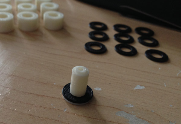
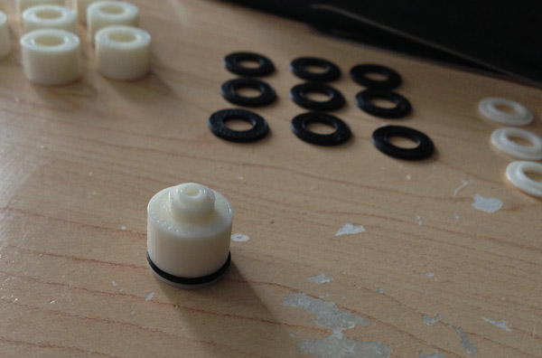
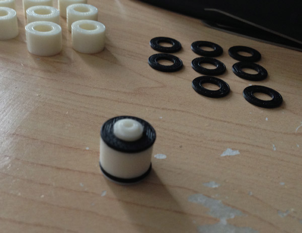
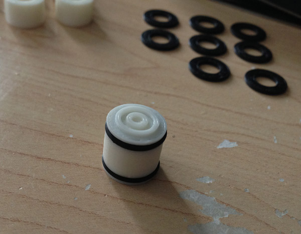
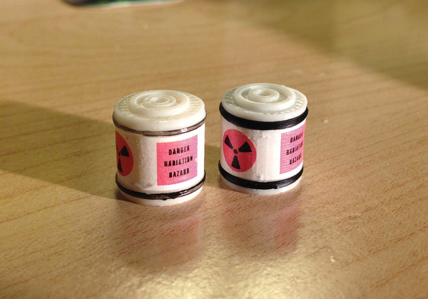
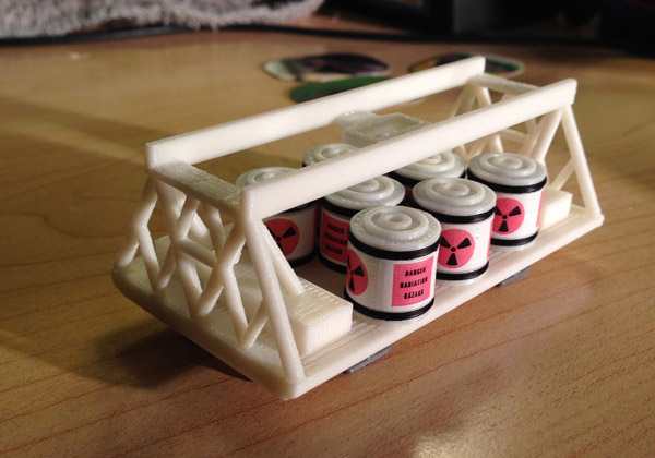
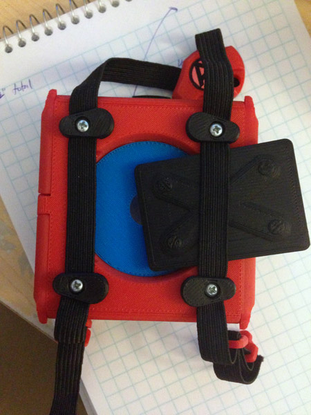
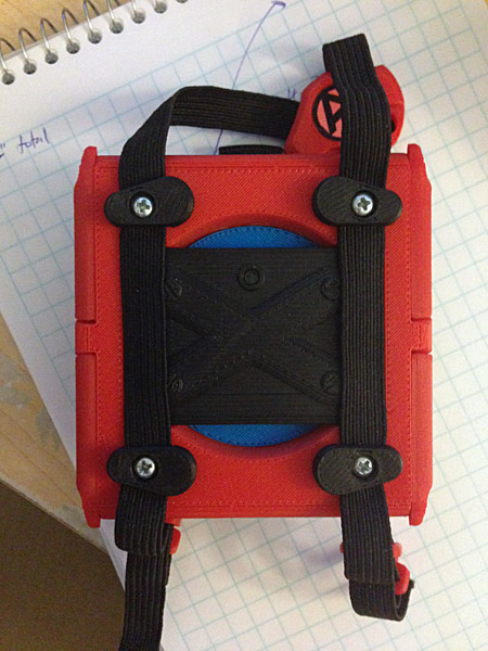
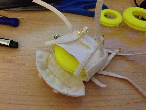
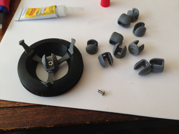
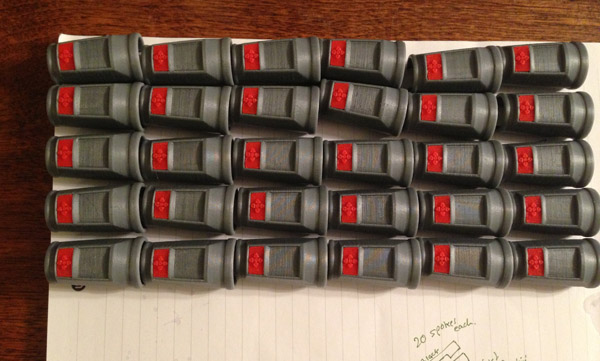
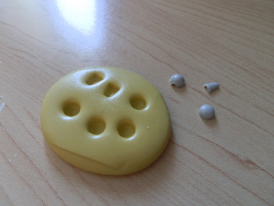
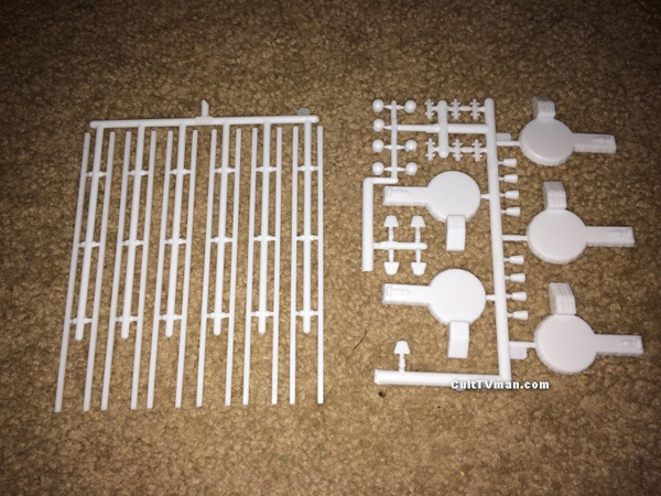
I also needed more pips, the housings that terminate and join the transport tubes, since the kit did not come with enough:

OLYMPUS DIGITAL CAMERA

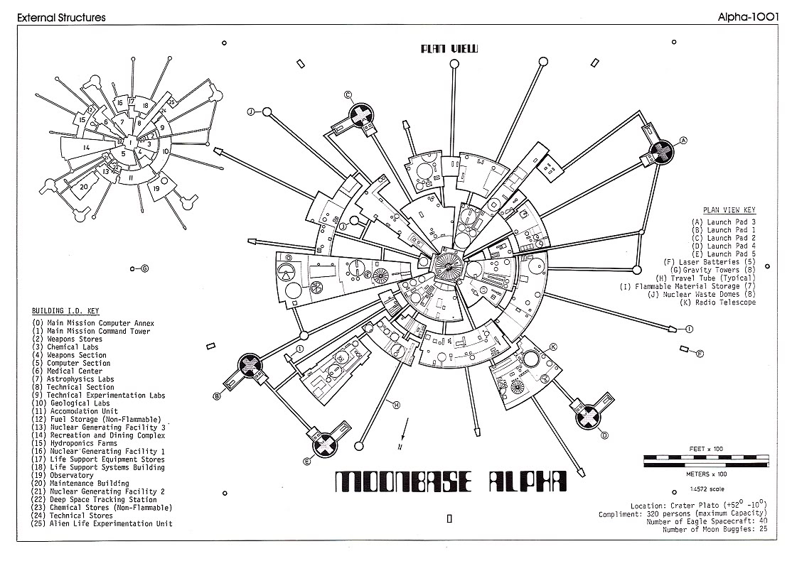
I printed this diagram out on several sheets, taped it together in scale, then used a piece of plastic over it, drew out the tube layout and base placement, and taped this to my lunar base for layout, just test-fitting the pieces on the layout:

OLYMPUS DIGITAL CAMERA

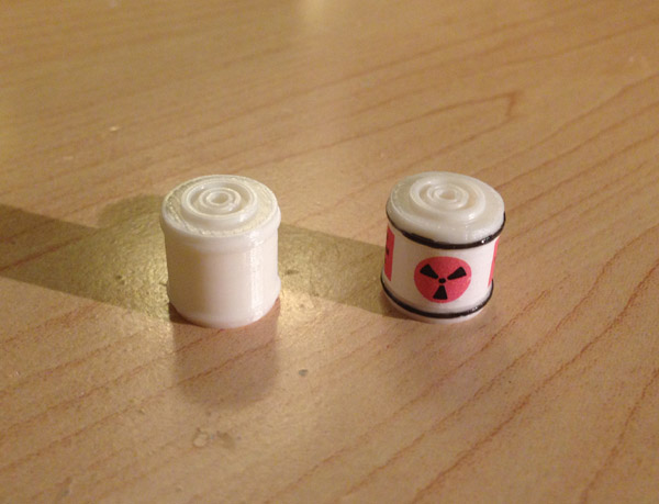
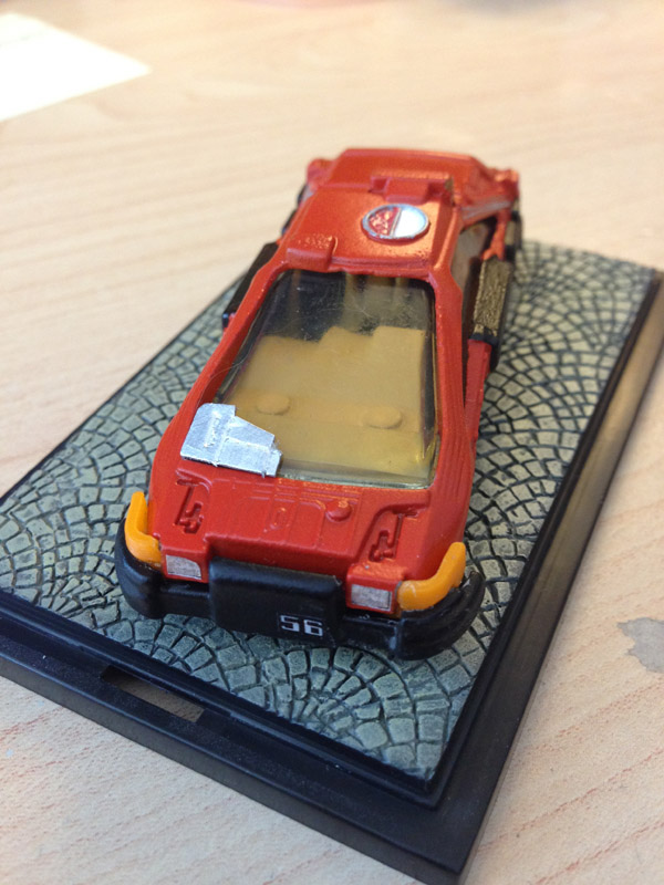
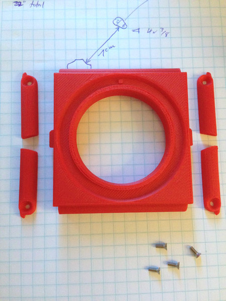
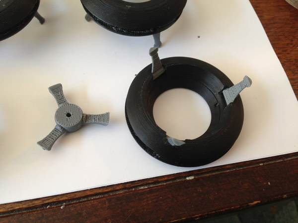
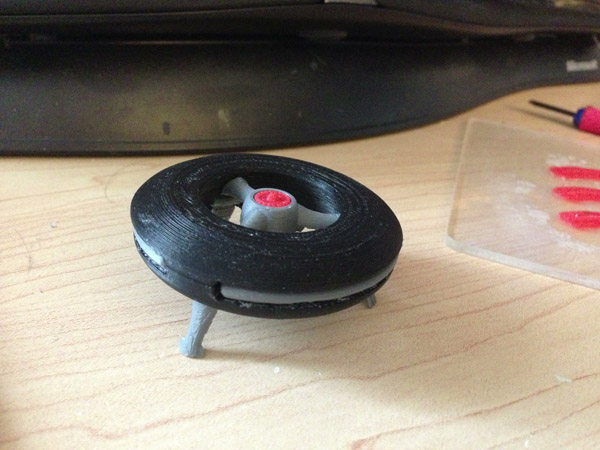
I was about to glue everything down when I got my 3D printer and decided to scrap the cast bases and model my own at true scale, complete with docking tubes (a piece missing from the originals) and re-lay it out again with minor changes needed to adjust the scale.

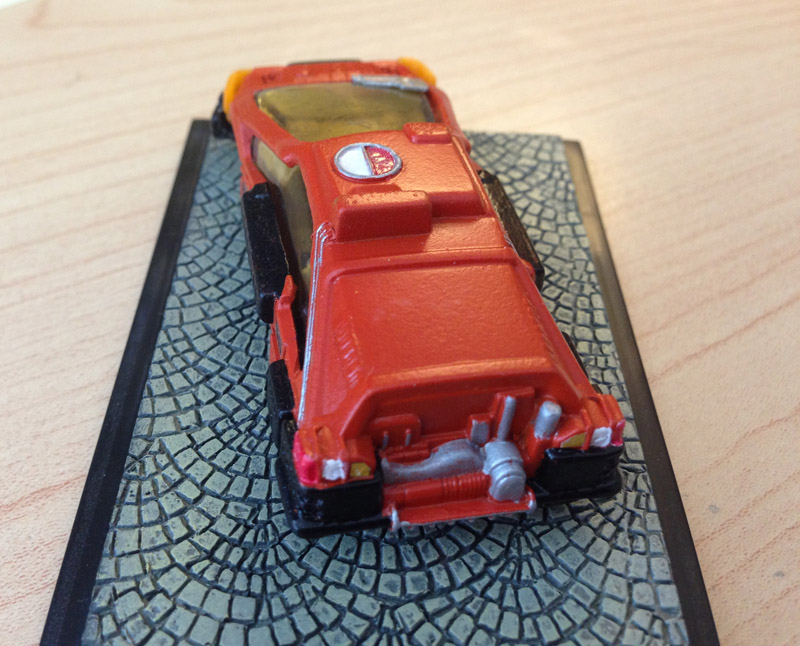
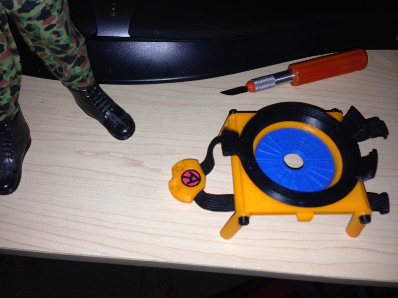
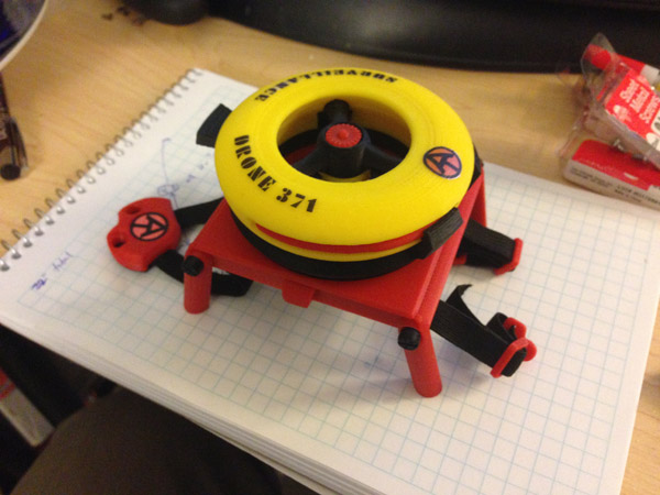
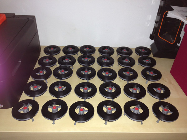
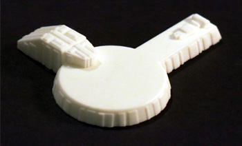
First, I reproduced the original launch pad, adding the docking tube, at original wrong scale:

OLYMPUS DIGITAL CAMERA

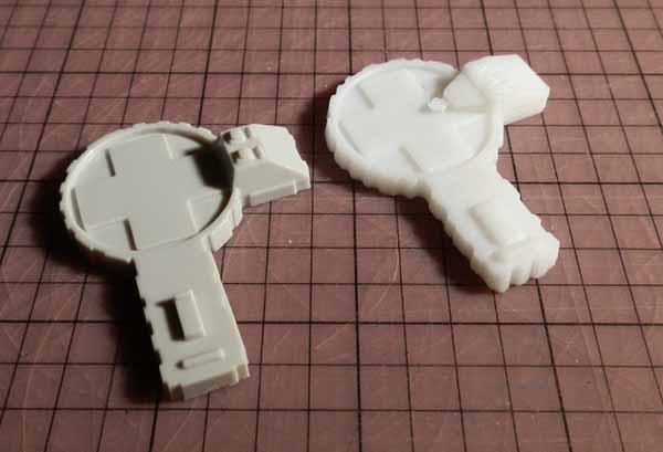
Later, I printed several of them at 80%, which is closer to accurate.

I was preparing those when I noticed that my styrofoam layout had been attacked by one or more of my three cats.

willow-wanda-rowan-3

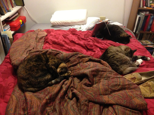
Oh, sure, they look all nice and peaceful and harmless lying there… but believe me, they are vicious diorama killers!

So I gave up on the project, it being winter now, and I had no way to recreate the moonbase effectively. Spray painting outside in winter is not a great activity. I gave up the project.

But then AMT/fundimensions go and announce they are again reproducing the original Moonbase Alpha kit – only get this:

This time they are producing it properly! The lunar base diorama will be more accurate, better and easier to assemble, fit together properly, and would not have the transport tubes molded in.

They would provide transport tubes to lay out.

mpc803-4

They would give us 5 launch pads, not 3, and at proper scale, with docking tubes! As well as the originals for those who wanted to reproduce the original inaccurate model kit.

mpc803-5

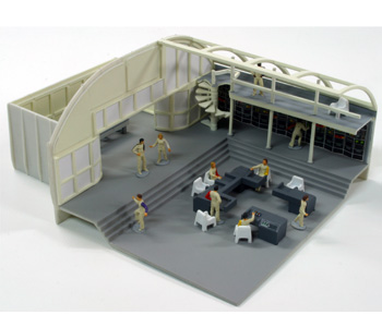
They would remove the Main Mission component from the layout and make it a stand-alone section of the model kit.

mpc803-2

They would give us not only the original overscaled Eagles, but six new properly-scaled Eagles as well!

round2-kit-parts

And this whole kit would cost under $40.00. Did I fall asleep and dream this?

NO!

It arrived two days ago! I will be spending some of this fall building it, and framing it when I’m finished. More as news develops!

Dinky Scaled Freighter/Pallet Pod Containers

In Space 1999’s first episode “Breakaway” we see Eagles transporting nuclear waste containers in freighter or winch pods for storage on the dark side of the moon. When the nuclear material begins to become unstable, winch pods are used to distribute them to alleviate the approaching critical mass.

eagle-unloading

Here are a few of the real Nuclear Waste Canisters as seen in the episode:
eagle-nuclear-waste-canister

Here is someone’s (sorry, I forget who. If you know, I would like to attribute it to the proper person) custom-made Freighter/Pallet pod made from parts of the Product Enterprise Eagle, to fit those models:
eagle-freighter-pallet-pod-real

A couple of months back I spent some time modeling a Winch Pod and a Freighter/Pallet Pod for my 4″ Konami Eagles and also for my 10″ Dinky Eagles.

One thing I modeled was the nuclear waste container. It was a single piece, a fairly simple 3D printed cylinder, with rings and a cap. I would paint the rings and create my own water-slide decals to give them the warning label the canisters had.

dinky-freighter-canisters-plain-painted-01

You can see I found painting the black rings to be quite difficult. Getting anything consistent or even was near impossible for me. I’m not that skilled at painting models.

So I decided – hey, I have a 3D printer after all, I don’t have to print these as a single piece. In fact I can print them in two colors in their individual rings.

So I set out to break the simple model down into a base with a post (that also forms the center of the cap at the top) with two black rings, a central body section, and a cap.

dinky-freighter-canisters-all-pieces

Here, the first black ring is slipped on over the base post/cap:
dinky-freighter-canisters-bottom-ring

Then the central body ring slides on:
dinky-freighter-canisters-body

Flanked by the top black ring:
dinky-freighter-canisters-top-ring

Topped off with a white cap that snaps to the central hub:
dinky-freighter-canisters-cap

I used clamps to hold them while the Super Glue was drying. Then I applied water-slide decals I designed and printed myself.

Here you see the painted version on the left and the printed version on the right: (I think I can probably thin out the rings a bit…)
dinky-freighter-canisters-painted-vs-printed-02

And here is what the finished Dinky Pallet/Freighter Pod looks like:

dinky-freighter-canisters-loaded

NOTE: For anyone who buys these models from me at my shop (Fourth D) on Shapeways, you may want to print the decal sheet I created. The two links below are to PDF files you can print.

Pod-Decals-Better-Layout

Pod-Decals-Instructions

You can print them on white waterslide paper either in laser or inkjet (make sure you have the right paper and follow instructions that come with the paper) or you can print them on simple white paper and use simple glue if you like. The decal sheet has both the Konami and Dinky scaled decals. Also, the instructions for the decals (for waterslide) are available here.


1:64 Scale Deckard’s Car Custom

I posted already about preparing my ERTL Blade Runner Deckard’s Car car for a custom version.

ertl-deckard-car-side

This is what the car looks like out of the box (or card). These are fairly rare these days and sell for about $25.00 and up, depending on condition.

Now you know Deckard didn’t have a big honkin’ “Blade Runner” logo on the back of his car, nor was it metallic brown.

Here is the box cover of the recent Fujimi model kit of the car in 1:25 scale. (I have this kit and will probably do something with it this winter.)

fujimi-deckards-car-1

Here is a restored or replicated version:
br-deckard-car-for-real-01

So here it is, finished.

Beside the original ERTL car:
my-br-deckard-car-with-original-01

I used some of the decals from the Fujimi sheet, scaled down:
deckard-decal-sheet

Details:

  • I painted the car a slightly rusty orange.
  • I painted the door bumpers black.
  • I cut out the thick vertical window posts.
  • I printed front orange curved lights over the bumpers. Due to the shape, I had to chisel out some space in the inside bumper
  • I painted the interior tan and black.
  • I put decals on the dashboard.
  • I painted silver detailing.
  • I printed custom headlight decals.
  • I printed custom decals for the 56 on the front bumper and the rear side.
  • I printed custom POLICE decals for the angled front sides.
  • I printed a decal for the top circle.
  • I painted tail lights.
  • I cut a small bit of glossy cardboard from a product package, scored it and painted it silver for the windshield guard.

my-br-deckard-car-left-01 my-br-deckard-car-rear-01 my-br-deckard-car-right-01 my-br-deckard-car-front-01

This is, supposedly, a shot of the real car taken some years back:
deckard-winfieldshop4


Adventure Team Backpack Surveillance Drone – Now in AT Colours

Last year I posted an article about my 3D printed Adventure Team set, the Action Pack Backpack Drone Surveillance. I designed it and 3D printed it on my Afinia H479 printer. Originally the drone was white with black structure and red highlights. The backpack was orange and black. These are acceptable Adventure Team colors.

at-drone-backpack-launch-base

But I decided I wanted to see how it looked in the more typical Adventure Team colors of red and yellow. I bought some Afinia Premium Red filament for the first time. (I had some Afinia Premium Yellow before, and I printed my Backpack Jetpack with that material.)

The result is pretty nice:

at-drone-backpack-with-drone-complete-01

Note: To apply my laser-printed water-slide decals I had to do some experimentation. These decals do not stick to ABS plastic. I discovered that spray-painting the top part with a satin clear coat paint, the decals would stick pretty well. Another spray coat over it and it should seal them down nicely. (Of course rough treatment may still make them come off.)

The Parts and Assembly

You saw how the drone was assembled (though in a slightly smaller scale it is an identical process) in my post about the Cotswold Deluxe Midnite Mission set.

The backpack frame, legs and screws:
at-drone-backpack-parts-01

The legs form the side of the backpack when being carried, and support the frame as a launch platform for the drone when in use:
at-drone-backpack-legs-assembled-01

Next, the harness. It is comprised of a 22-inch strip of .375 inch wide black elastic. First, I fold the elastic in the middle and place it into the space modeled into the harness bracket front half. While this picture does not show it, the red half has a channel modeled to fit the elastic on a folded angle.

at-drone-backpack-harness-parts-01

Then the two short, stubby screws are screwed into the black back plate through the elastics to hold it firmly:
at-drone-backpack-harness-screws-01

Here are the four black strap brackets that will hold the elastic harness in place on the frame:
at-drone-backpack-harness-brackets-01

The elastic is carefully placed so there is a 7cm distance between the top bracer and the harness chest piece. A screw holds the elastic and the bracer in place firmly. Then the elastic is stretched somewhat (consistently) to the lower bracer and that is screwed onto the frame. There is equal tension between the two bracers for a purpose:
at-drone-backpack-harness-attached-01

Next the strap adjuster and harness clips are placed onto the elastic strips:
at-drone-backpack-strap-adjusters-01

The completed harness:
at-drone-backpack-harness-complete-01

Next, the solar cell (which charges the drone’s recharging batteries when it is in the air) is glued to the circular aperture:
at-drone-backpack-solar-cell-01

On top of this the drone’s holding tray is glued: The drone fits perfectly between the three clips, and the top clip is used to free it by pressing gently until the drone is released from the grip of the tray.
at-drone-backpack-drone-tray-01

Here you see the touch-screen tablet used to fly the drone, and to monitor the drone’s camera capturing ability. This is a single printed piece with clear-coat and a glossy printed screen spray-glued (with permanent glue hopefully) to the surface:
at-drone-backpack-control-tablet-01

Ok, I’m going to claim some cleverness now. This tablet stores perfectly flat in the backpack frame in a cavity modeled to fit it, held in place by the harness straps:
at-drone-backpack-tablet-storage-01

Here it is, stored fully:
at-drone-backpack-tablet-stored-01

Lastly, for the backpack, these four black “bolts” are glued onto the legs (so as not to interfere with the screws) to finish off the look:
at-drone-backpack-leg-bolts-02

Et voila:
at-drone-backpack-with-drone-complete-01

Cotswold Collectibles – Deluxe Midnite Mission Set

cots-cover-image-midnight-mission

At the GI Joe Convention in Dallas in April I met Greg Brown of Cotswold Collectibles. I had sent him some of my 3D print samples some months earlier and he expressed interest in doing some project work together for Cotswold Collectibles, which had recently begun to issue mail-out catalogs in full color again, featuring some Adventure Team-themed outfits and full sets

He showed me plans he had for a complete stealth set which harkens back to the good old days of the GI Joe Adventure Team. Here was a modern take on the Spy Island set, and it included a black and silver version of my AT Surveillance Drone which I had designed last year and 3D printed. The drone featured in one of my diorama entries at the Convention, seen here:

IMG_1174

The drone, printed in white, hovers above the scene, suspended by a thread on an armature.

I began work immediately. First, the construction of my drone was a bit flimsy, especially the working camera head which pivots around a hub using a tenuous connector that was easily broken and came loose easily. I opted to fix that by using a screw. Second, the struts that hold the central hub to the outer ring were individually printed and had to be glued together in another relatively tenuous connection.at-surveillance-prototype-3

My first improvement was to combine the three struts with the central hub for a single, strong part. Then I created notches in the ring and pins in the struts so the hub part could snap to the body accurately and strongly. The rest remained relatively unchanged; the legs (not seen in this photo) which form the bottom segments of each strut hinge down as landing gear.

But the drone had to fit into an existing Cotswold backpack which Greg sent me. I found that I had to scale the drone down to 75% of the original. This meant that moving parts may not work, since tolerances at that scale would be different.

cots-drone-scaling-test-01

(I test print in neon yellow to make sure I don’t confuse them with final parts. And I have a lot of neon yellow with not much use for it.)

To my surprise, I printed three test drones. One at 50%, one at 66.66% and one at 75% of the original size. To my utter shock and astonishment, each one functioned perfectly when printed. Even the 50% scaled version had working legs that folded without an issue.

The 75% version fit the backpack perfectly.

cots-drone-fitting-backpack-01

I began printing a couple of test models, sent them to Greg for approval, then began printing in earnest.

Here, I assemble the drones:

The bodies are split into an upper half and a lower half. The lower half has spaces for the legs to hinge down.
cots-drone-leg-assembly-01

Small pegs align the upper and lower halves. The legs are held in by square blocks that, when pushed into place, form a perfect hinge space.cots-drone-leg-assembly-02

The pegs are put in place, and the top glued to the bottom, clamped down by six strong clamps.cots-drone-body-clamping-01

Next the hub gets snapped in place and glued.
cots-drone-hub-assembly-01

Then a small screw is used to screw the camera head to the hub.cots-drone-camera-assembly-01

Then (not shown here) the camera is placed in the camera head by friction so it can swivel on its axis freely.

Then the repulsors are glued in place and a jet vane is glued to the top of the hub.
cots-drone-complete-01

And after a heck of a lot of work, I had 30 ready to go:
cots-drone-all-done-01

Then I had to design the arm controllers. I had a simple idea in mind and wanted it to be a single piece. But the design made me want an accent color so I made the control pad red on a silver cuff that can snap to a GI Joe’s dressed arm.

cots-drone-controllers-all-done-01

The space below the control pad in red is reserved for a sticker which will show the view as seen from the drone’s camera.

So here are some pictures Greg posted featuring the finished prototype:

cots-midnight-mission-set-01 cots-midnight-mission-outfit-05 cots-midnight-mission-outfit-04 cots-midnight-mission-outfit-03 cots-midnight-mission-gear-01

And here is the catalog, which I got in the mail a couple of weeks back:

cots-catalog

P.S. I am currently at work on my second Cotswold set. News on that as I am allowed to post it. Stay tuned.