Afinia – Facebook Front Page – My Ornaments

I decided this year to begin a new tradition. Every year I have a 3D printer I will design and print a Christmas Tree ornament using my latest and best printer. Hopefully I will buy new printers as they evolve and become better and much like my first dot-matrix printer, I have had a paper printer of one form or other most of my adult life. This year I decided to use my very first 3D printer, the Afinia H479, and make a Christmas Tree ornament that meant something. So I made a miniature version of the ornament printing a Santa hat ornament.

OLYMPUS DIGITAL CAMERA

A bit meta, as most people who knew about this pointed out. I liked that.

So while this ornament sits proudly on my own tree right now, I also printed one to send to my mother, and also one to send to Afinia, the makers of this printer.

They liked it so much that they wanted to print one for all of their employees, and asked if I would mind sending them the files. I did not mind. So I sent it to them.

(If you want them, you can also get them here. What? You want them for free?)

So Afinia liked it enough that they sent me this image of the ornaments printed in all of the Premium colors they have available:

afinia-ornament-assortment

Apparently they liked it enough to make it their facebook front page image:

afinia-facebook

Afinia also sent me a reel of white premium filament, a printer nozzle and a sheet of their new Build Tac sheeting to print on (which I am loving!)

I’m already thinking about next year’s ornament.


GI Joe Adventure Team Action Pack Flight Pack

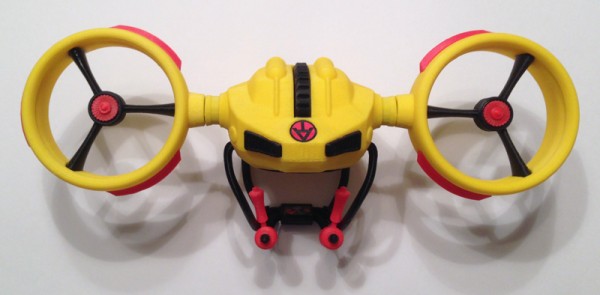
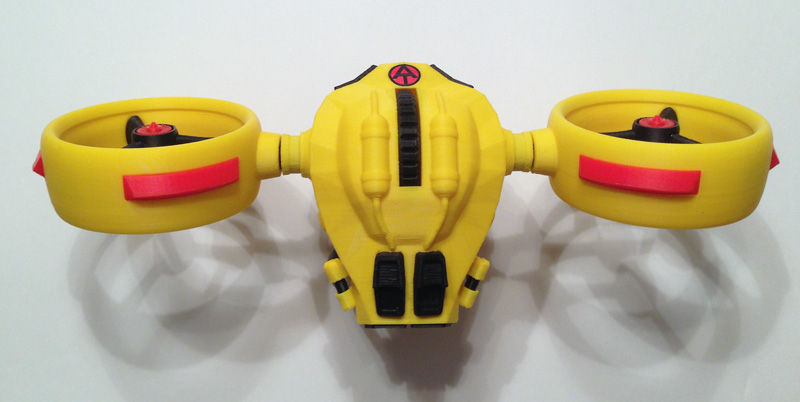
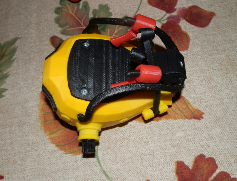
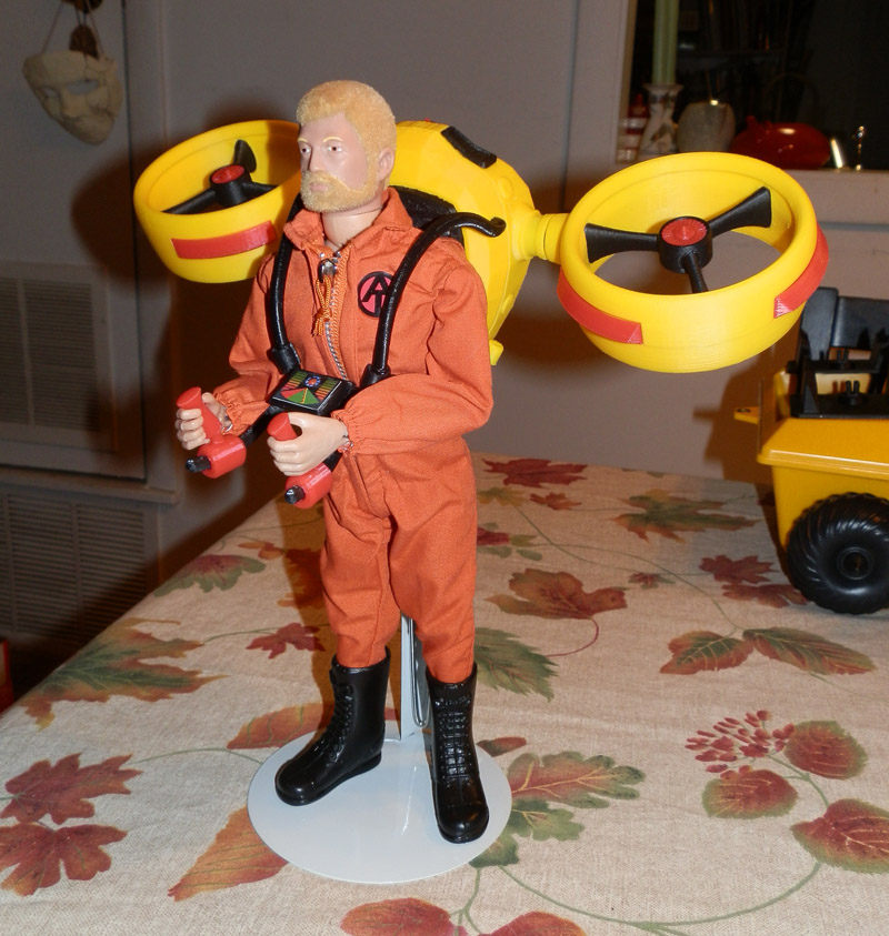
I recently made a slight change to the name of my GI Joe Adventure Team Action Pack Jet Pack. It is now the GI Joe Adventure Team Action Pack Flight Pack. I did this on the advice of a fellow collector who said that it didn’t really have the look of a Jet Pack.

atapfp-jetpack-back

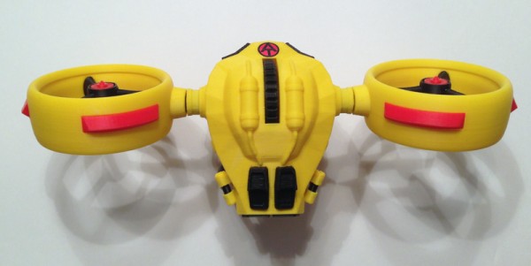
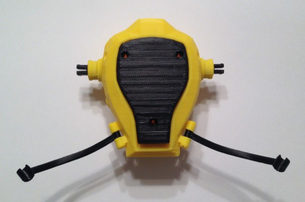
However, this design has (fictionally of course) a jet engine in the back pack that forces air out through the engine housings for a forced-air effect that provides upward thrust without jet-flame output that would burn the pilot. But since it doesn’t really look like a Jet Pack, I thought I would take the advice of a fellow collector and call it a Flight Pack.

atapfp-jetpack-top

The otherwise overly long name stands, however, since it means something.

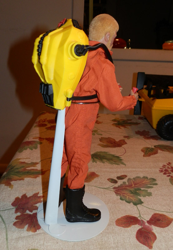
It’s for GI Joe. It’s for the Adventure Team. It is intended to be (retro-actively) a part of the GI Joe Adventure Team Action Pack line, which were generally useful bits of equipment that in some way folded up and were worn on the back for transport when not in use.

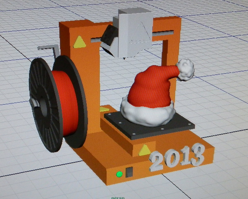
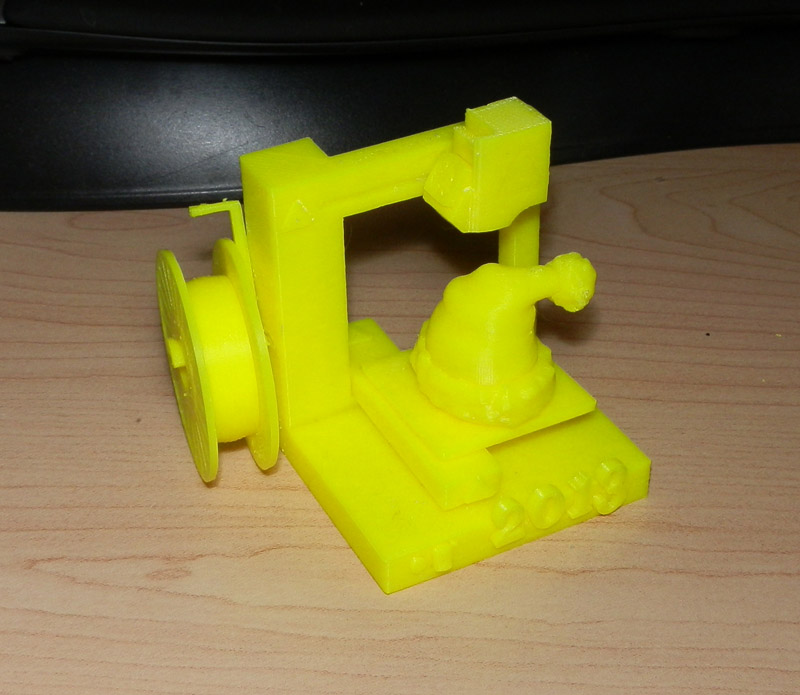
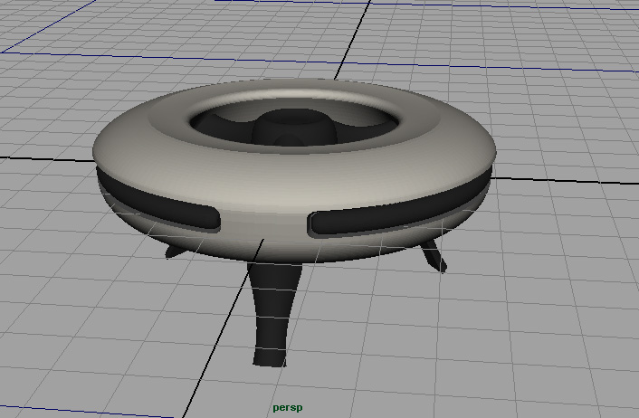
This toy that I designed in 2013 has been an important thing for me. I came up with the design, modeled it, with functionality and fit in mind, then I printed it over and over on my Afinia H479 printer until the parts all worked, and even now I’m refining it.

Some news:

Publishing

I published the model on 3DAGOGO. 3DAGOGO is a pay-per-model site and I’ve sold a few pieces there, mostly the Airship I designed.

Afinia

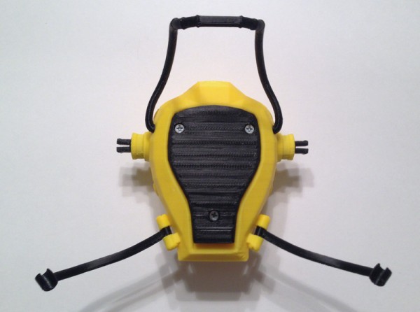
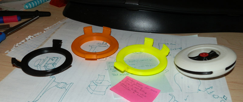
Afinia asked to use this model in their CES booth, which was a thrill to me. I sent them both a yellow and a black (stealth) version along with a GI Joe figure to model one on. It will be on display at CES in their booth. I will post pics if they send me any.

Design Refinement

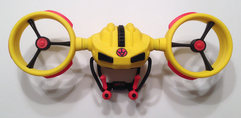
This is v1.2, which takes most of the design from the first prototype, but adds some things and changes some things to make printing easier and to make assembly easier.

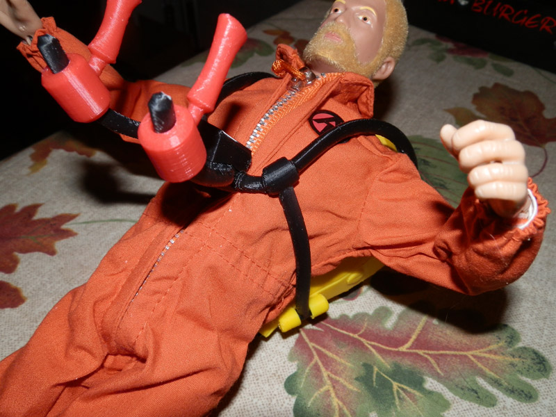
Changes to this version include a more open clip design to clip the under harness arms to the main harness, and a better system to clip the swing-down harness control arms. I straightened them out, because before, if you rotated the joysticks all the way around, the subtle curve in the arm and the joystick bent the arms until they broke. That should not happen now that the arms and joystick cuff are perfectly cylindrical. Also, I made the harness control arms use two pieces so I could screw them to the main harness front, instead of trying to force the pieces together. This often broke the pieces. This version is a tad loose, though, so expect another minor change.

V1.1 had a control screen on those arms, but the screen was too tall. When the control arms were lifted up while the pack was being worn, the screen prevented the arms from going up, becuause it tried to go into the figure’s body. This version flattens it and should work better. I’m still working on that.

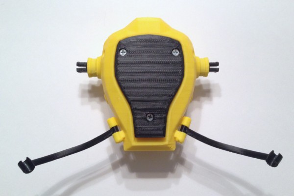
Mostly, this is otherwise similar to the other version with some changes to the screw holes to allow easier printing (the first few I made printed fine, but later the printer kept hitching on the screw holes because of their starburst design.)

I also puffed out the cushion a little. The printer doesn’t allow it to print very smoothly, but it’s better, I think, than the original.

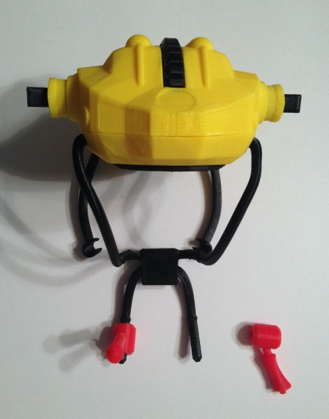
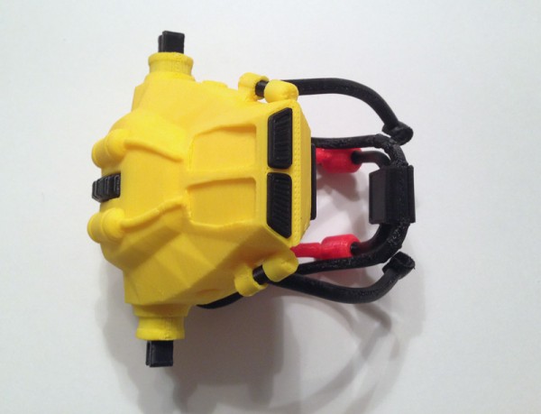
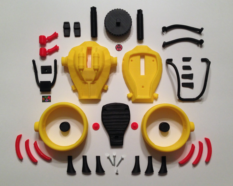
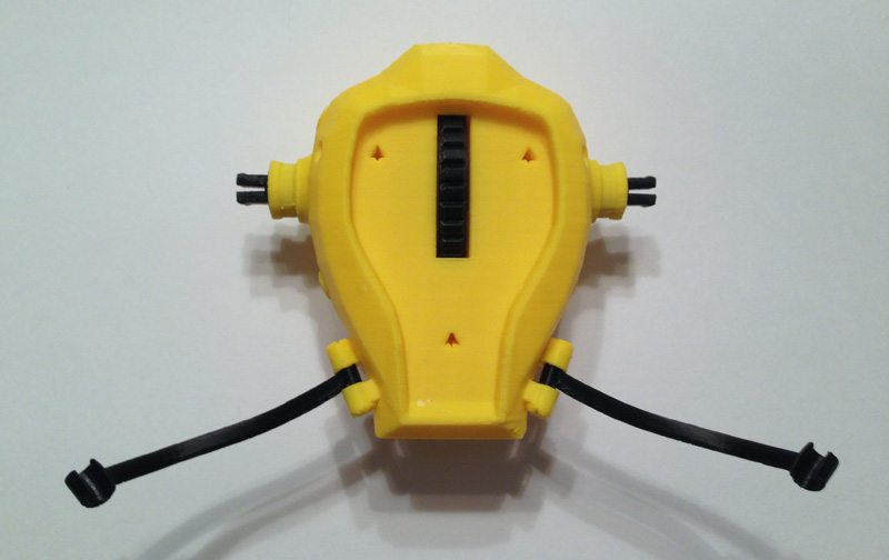
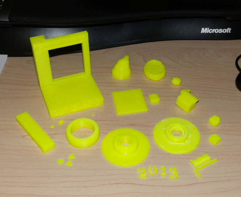
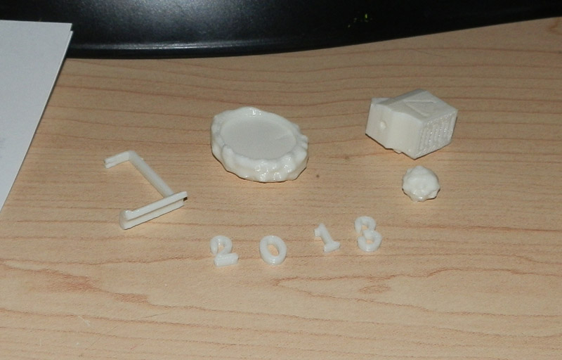
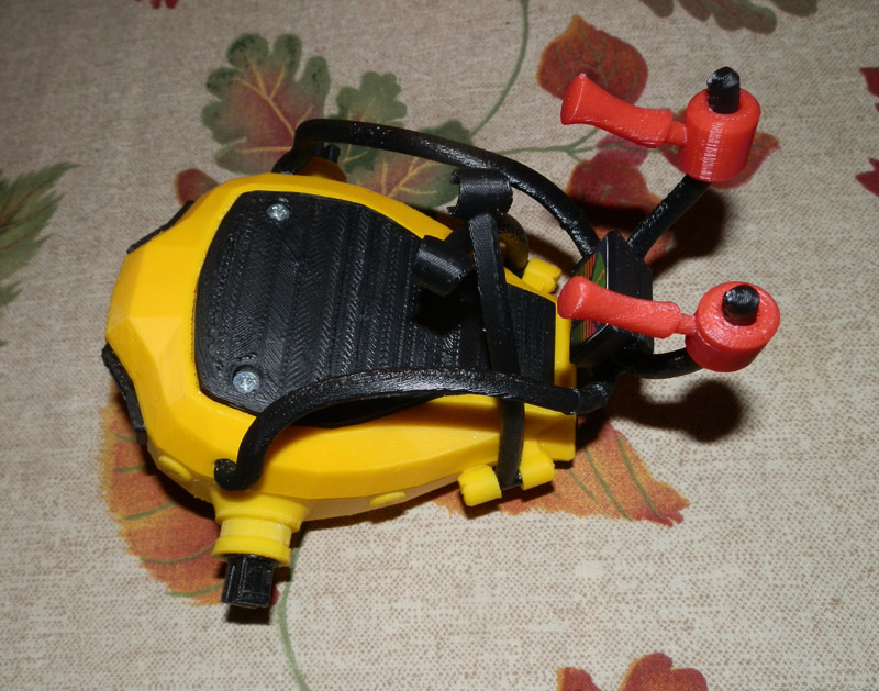
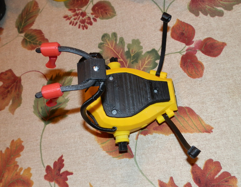
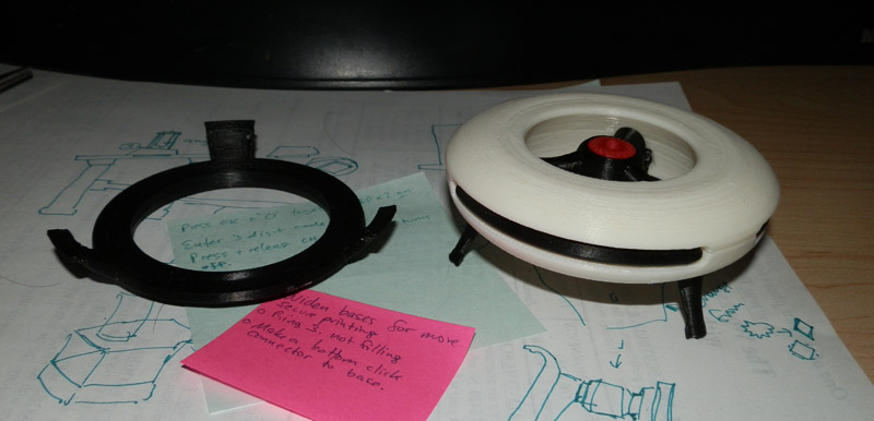
Here are all of the parts for V1.2 of the Flight Pack:

atapfp-all-parts

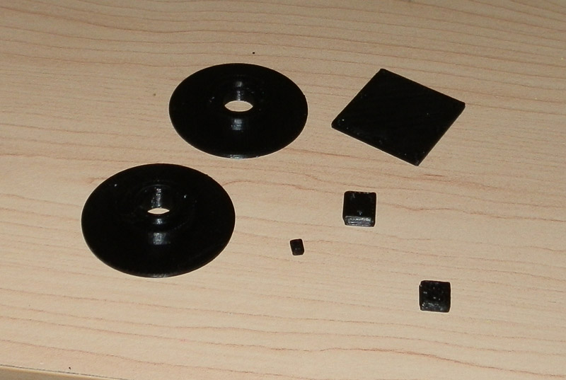
37 printed parts in 3 colors. 4 screws. 2 printed pieces of paper, (glossy paper, on sticky back works, or glue it.)

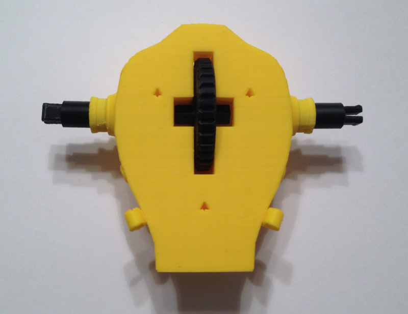
And here is the assembly process, step-by-step:

atapfp-thumbwheel-engine-mounts
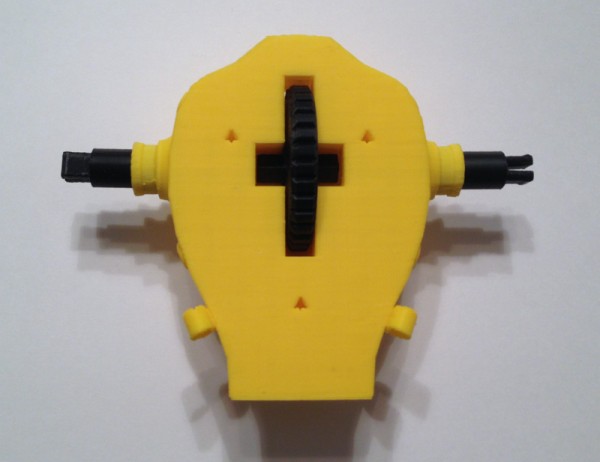
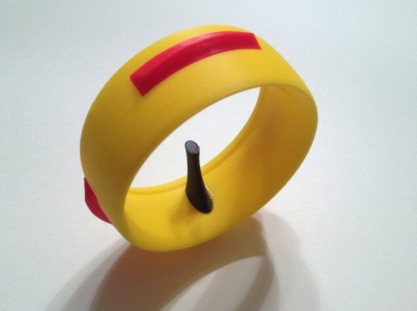
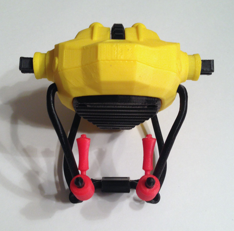
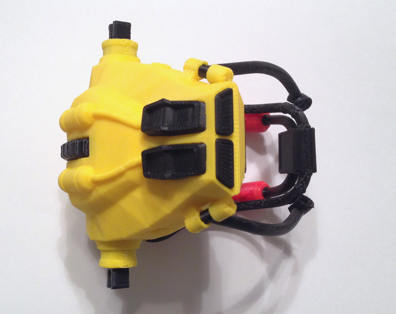
Push one engine shaft into the body shoulder hole, and the other. Place the thumbwheel in the body slot. Rotate the two engine shafts until they fit onto the thumbwheel. Make sure the forks of both engine shafts are aligned (not aligned in the photo.)

atapfp-thumwheel-engine-mounts-snapped
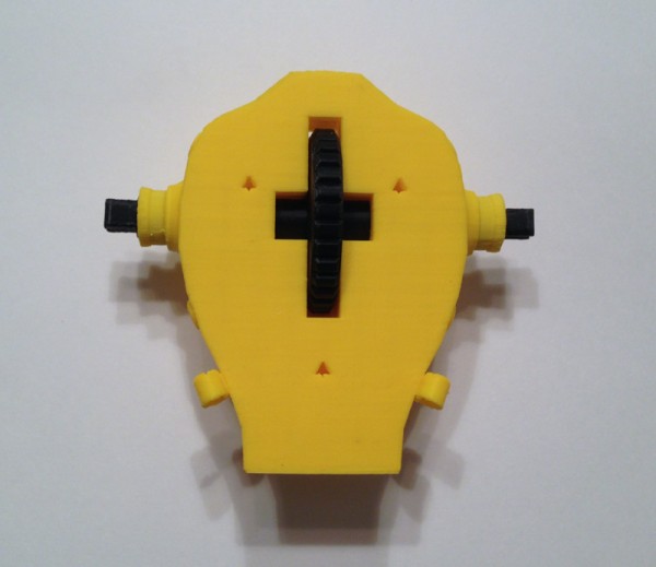
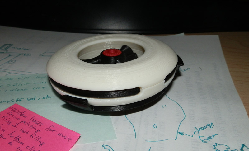
Push the two engine shafts together until they snap onto the thumbwheel.

atapfp-bottom-harness-arms-mounted
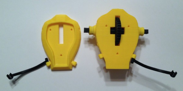
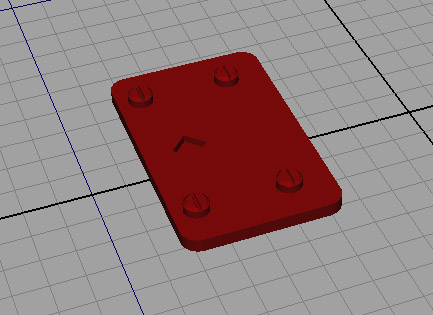
Ensure that each harness lower arm is aligned correctly. Place one in the lower bracket (on the body front part) and the other in the upper bracket of the main body piece. This is done so when fitting the two parts together, they can be wiggled into place. This is much harder if you try putting both harness parts in the same body piece.

atapfp-bottom-harnesses-body-joined
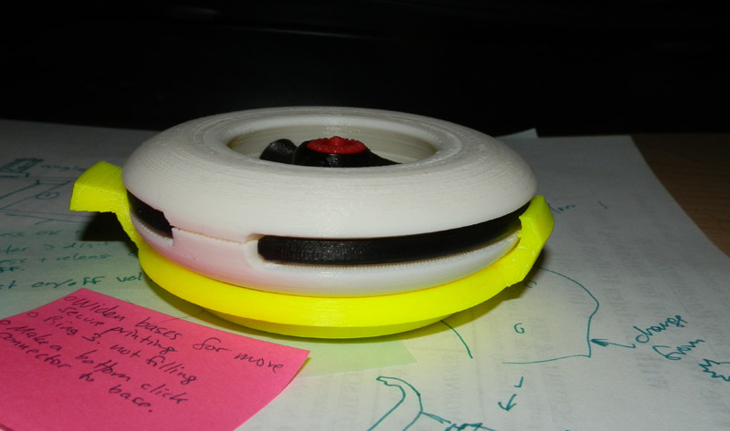
Fit the body front and body main parts together, ensuring the harness arms fit into the four brackets nicely.

atapfp-back-saddle-placed
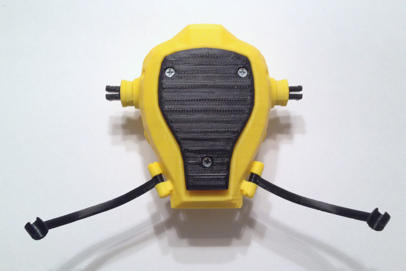
Put the back saddle cushion in place.

atapfp-back-saddle-screwed-down
Use the three longer screws to screw the cushion, body front and body back together. Do not overturn the screws. Once they are tight they should be fine. Further turning will simply weaken the holes.

atapfp-shoulder-harness-placement
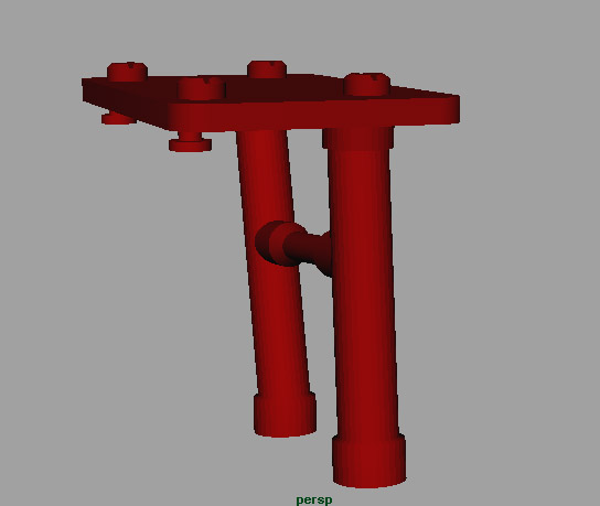
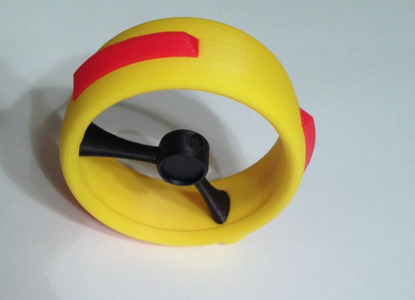
Place the main harness into the two holes in the body front piece by gently prying the frame apart.

atapfp-shoulder-harness-pushed-in
Push into the holes until they stop. Test rotation.

atapfp-harness-handles-disassembled
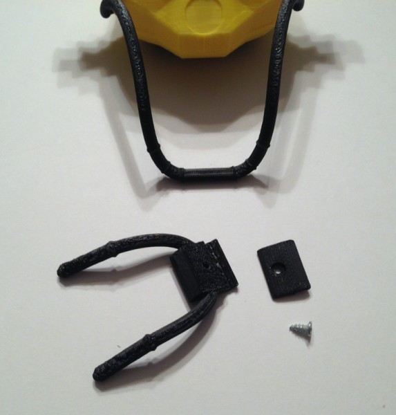
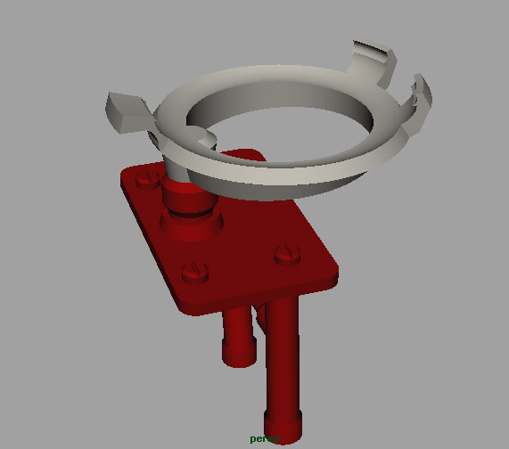
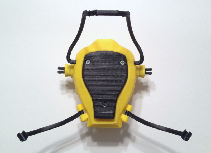
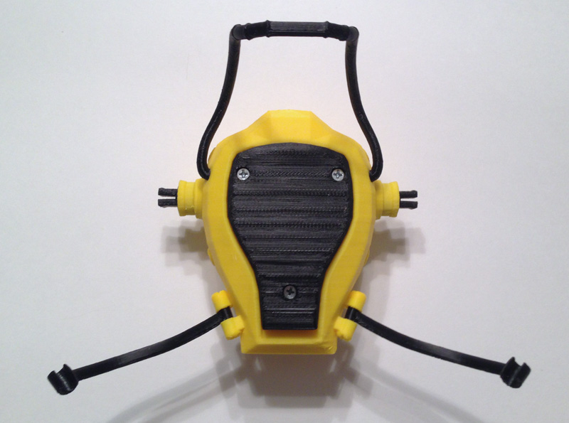
Prepare the harness handle section.

atapfp-harness-handles-assembled
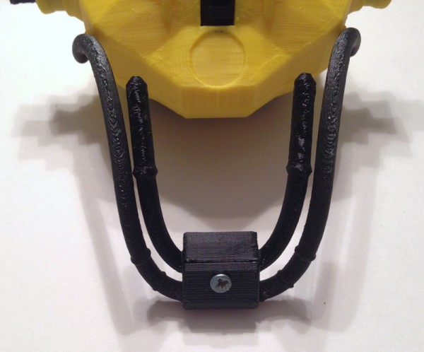
Place the two pieces over the flat front part of the main harness and use the small screw to attach the parts.

atapfp-harness-handles-joystick-one
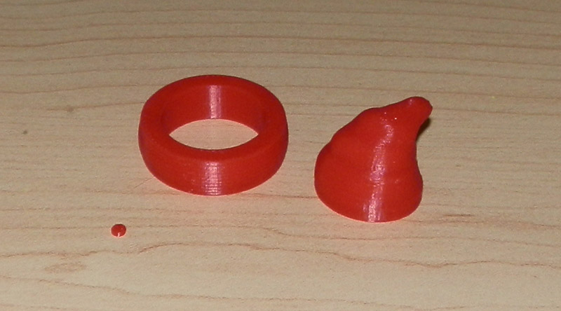
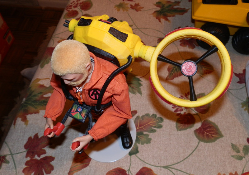
Push one joystick onto the control arms, rotating as you go.

atapfp-harness-handles-joysticks-both
Attach the second joystick by rotating and pushing.

atapfp-vent-upper-left
Using Krazy Glue, attach the upper right vent by fitting the vent into the aperture.

atapfp-vent-upper-right
Do the same with the upper left vent.

atapfp-vent-lower-right
Glue the lower right vent into the space provided.

atapfp-vent-lower-left
Glue the lower left vent in place.

atapfp-vent-back-right
Glue the lower back right jet vent into the gap. It should snap nicely in place.

atapfp-vent-back-left
Snap and glue the lower back left jet vent in place.

atapfp-control-screen
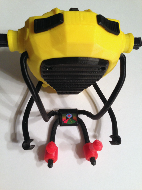
Glue the control screen into place.

atapfp-at-logo
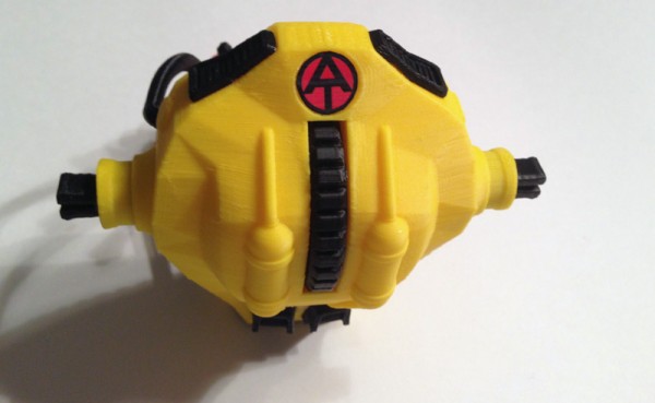
Glue the Adventure Team logo in place.

atapfp-engine-housing-vents-disassembled
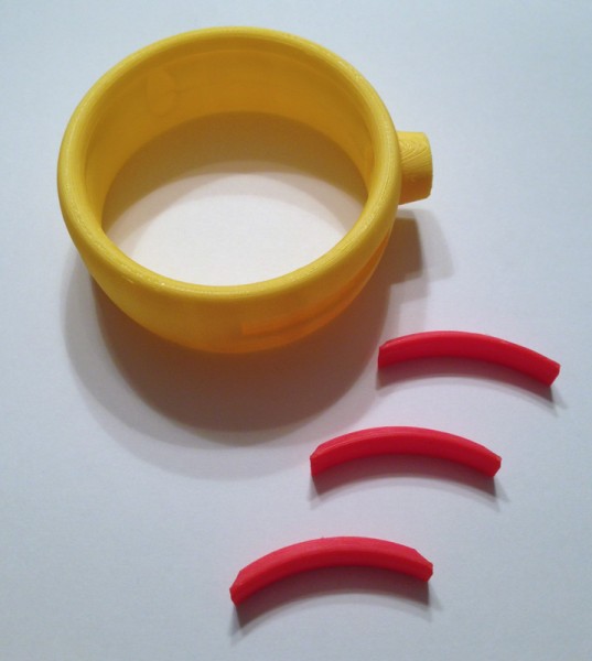
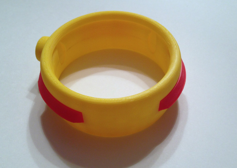
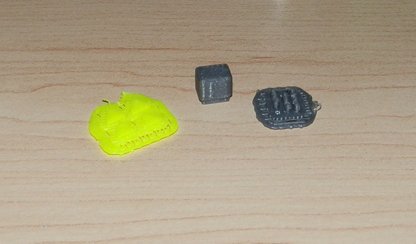
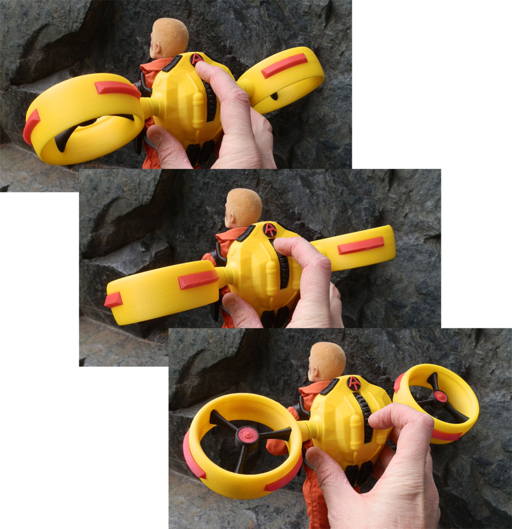
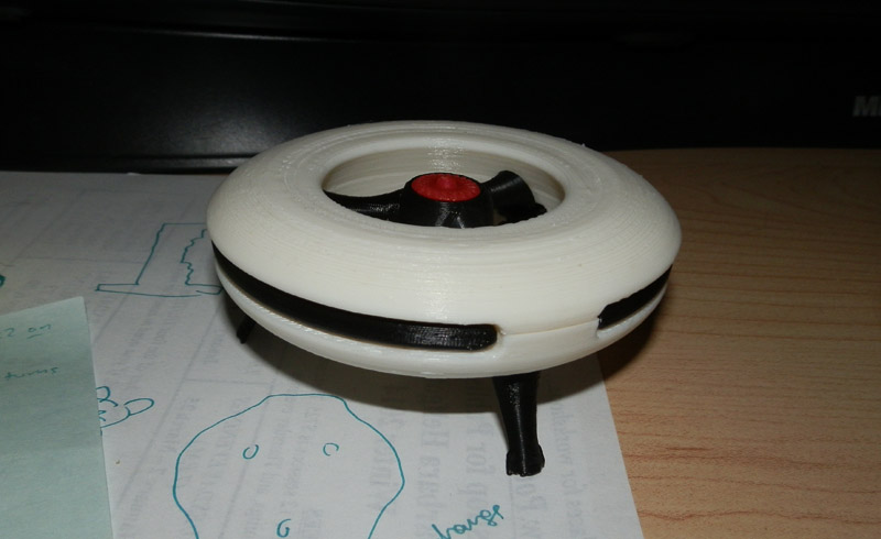
Prepare the engine housing and the three vents.
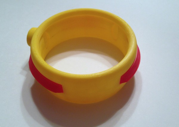
atapfp-engine-housing-vents-assembled
Glue them in place.

atapfp-engine-brace-first
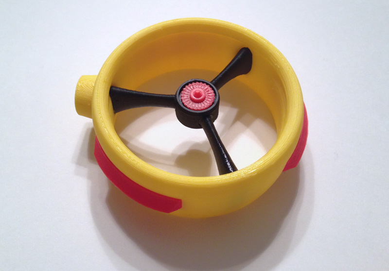
This part is particularly hard. Coordinating three of these is a difficult feat of manual dexterity. So we glue the first engine brace in place so the flat part is towards the top (the uppar part has the ring aperture inside to let jet air flow over the body.) The curved part points downward.

atapfp-engine-brace-second-hub
Then glue the second bracer in place and glue the hub onto the two braces being very careful that the square hole in the hub is flat with the engine housing arm grip (the round part that connects the engine housing to the body.)

atapfp-engine-brace-third-vane
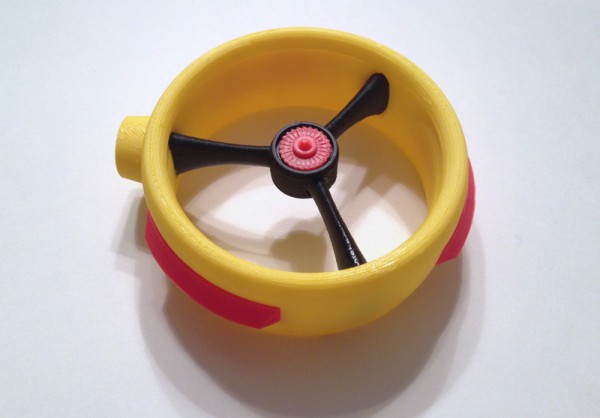
The next operation is the most difficult. Placing a bit of glue into the third gap in both the engine housing and the hub, push the bracer into place. This can be quite difficult. When it fits together, the three bracers hold the hub in place by sheer pressure, but we glue it because pressure can break the connection. Then glue the engine vane into the center of the gap.

atapfp-engines-on-side
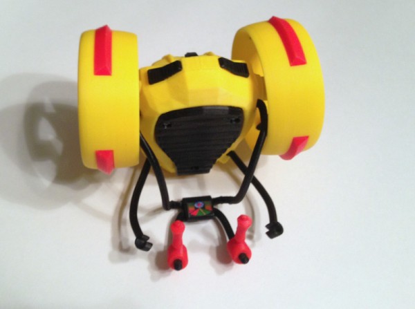
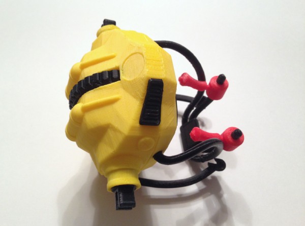
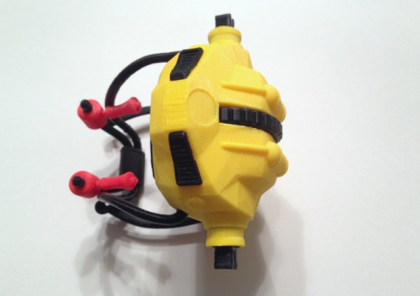
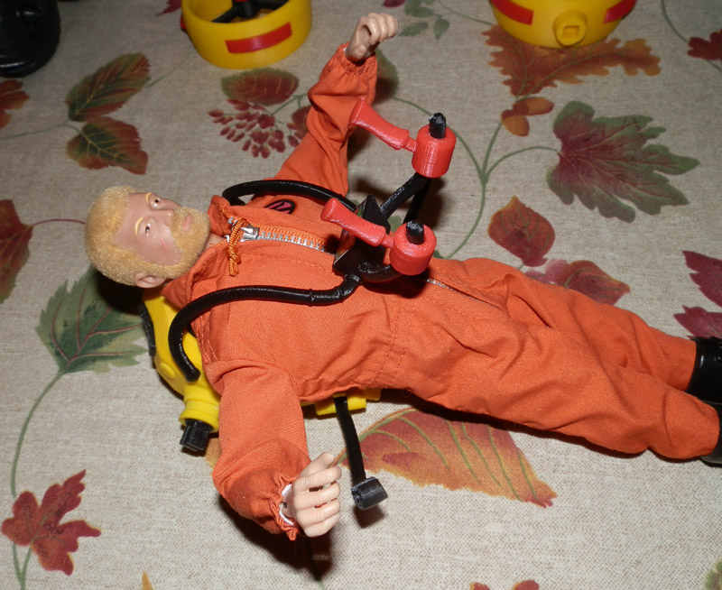
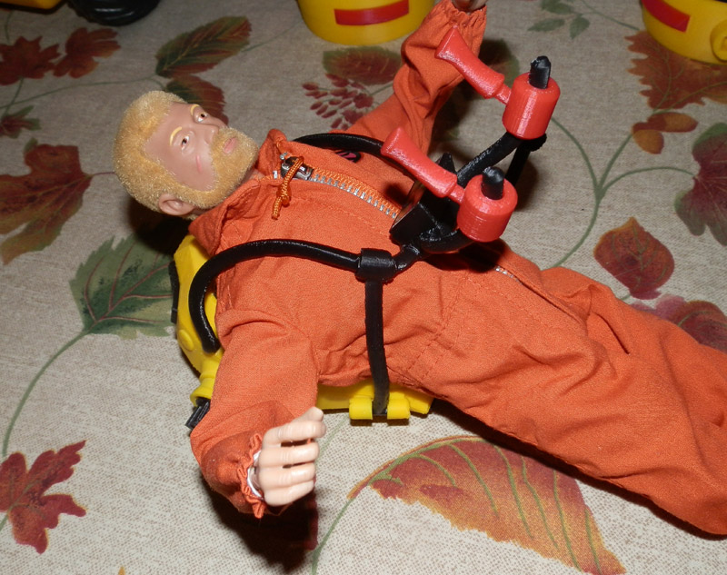
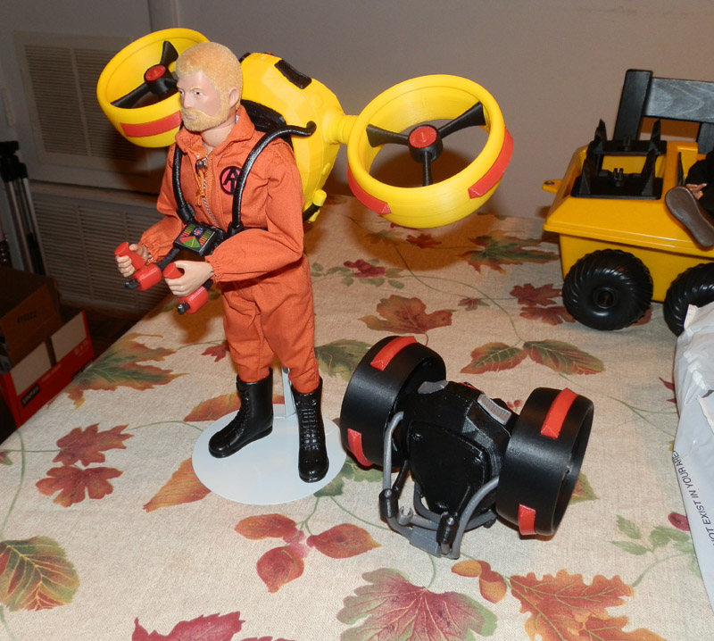
For traveling on the back of the pilot, and for transporting via ATV, push both engine hubs into the engine mount shafts.


The 3 Things You Are Doing That Will Ruin Your Life

The 3 things you are doing that will ruin your life:

1) Reading Listicles
2) Reading Listicles
3) Reading Listicles

Listicles are generally blog articles (because no legitimate paper publication would entertain putting them in print) that usually begin with “The 17 things your Teen is doing behind your back” or “The 9 things your husband does to find out if you’re cheating”.

They suck in vulnerable clickers (which is all they care about) to increase the traffic on their sites, using the curiosity pull, and a headline that claims to know the definitive number of things that will sate your undying curiosity and save your endangered life.

What you end up with is some bored or underworked blogger with no more wisdom than you have (and probably a fuckload less because he/she’s probably in his/her twenties) writing a list of things that match some topic they were either assigned to write, or come up with out of the daily irks in their own lives, or something they believe will suck gullible readers in.

Propagate Listicles and what do we get? An internet clogged with bullshit. Now that may seem like a redundant concept, and probably is these days. But what it does is de-legitimize legitimate press (you remember… journalists…?) No, you probably don’t remember those. There hasn’t been a sighting of one in years now.
So please. Just skip the listicles, and for godsake, stop posting them to facebook!

2013 Christmas Ornament – 3D Printed

Someone gave me a great idea – model and 3D print an ornament for the Christmas Tree.

I thought this was an absolutely great idea. Since Christmas Tree ornaments are an important part of our family tradition, I thought I would make one this year, the first year I got my 3D printer, and every year after, to show the evolution of both my ability, and, I hope, the technology.

So for the first one, the subject matter seemed obvious!

The Afinia H 479 printer which had just finished printing a Santa hat!

So I started sketching, and then began modeling. Here is the 3D model:

OLYMPUS DIGITAL CAMERA

(Sorry. The photo is taken using a camera off my monitor because my PrntScrn button just chose this moment to stop working. I will require a reboot and I’m busy right now.)

The one issue I couldn’t really solve was the color of the printer. The real deal is kind of like primer, but glossy. It’s a maroon color. I have no filament that even comes close, so I chose orange to be a bright, happy color. I could also have used green, which would also hammer home the Christmas theme, but it seemed a bit much. Still, I may go with green.

Anyway, to test, I printed a prototype which, as usual, outlined several issues to fix.

You can see here some of the issues, but there are others you can’t see as easily. Note the separated sections of the text: “2013”. I have to thicken the thin lines because the printer has a minimum size tolerance for area.

OLYMPUS DIGITAL CAMERA

Also easily seen here is the broken spool holder. The shaft is too thin.

After fixing those issues and re-printing some parts, here is the first assembled (day-glo yellow) prototype:

OLYMPUS DIGITAL CAMERA

There is a hole for a screw eye, which may be too small, but that’s easily fixed too.

Note: One reason to print test prints is to make sure everything fits. It’s only theoretical in the model, you have to print it to see. This pointed out several issues, and one was the height. The printer is too short in this test print. Fixing it for the real print.

Here are the black parts:

OLYMPUS DIGITAL CAMERA

  • Two spool halves
  • The Initialize switch
  • The print bed
  • The print bed heater
  • The print head fan

Here are the white parts:

OLYMPUS DIGITAL CAMERA

  • Spool Holder
  • Hat Fringe
  • Print Head
  • Hat Tassle
  • 2013 Year

And the red parts:

OLYMPUS DIGITAL CAMERA

  • Red LED (in case I want it. I am also printing a green one. The LED flashes red and green on the printer.)
  • Reel of red filament
  • Santa hat

And the final parts, in day-glo yellow and silver:
OLYMPUS DIGITAL CAMERA

  • Warning labels
  • Z-Axis Motor
  • Nozzles

And here’s the finished product!

OLYMPUS DIGITAL CAMERA


Setting Up GI Joe Action Pack Jetpack – A Guide to Not Breaking It!

The yellow jetpack is wrapped in bubble wrap in three pieces: The main body, and two engine housings.

1. First, lay the jet pack on its back.OLYMPUS DIGITAL CAMERA

2. Swing down the control arms (with joysticks).OLYMPUS DIGITAL CAMERA

3. Lift main shoulder harness up, and open up the two under arms.OLYMPUS DIGITAL CAMERA

4. Placing GI Joe’s head in first, situate him so the shoulder harness fits snugly over his body.OLYMPUS DIGITAL CAMERA

5. Lower the harness, keeping the control arms straight out.OLYMPUS DIGITAL CAMERA

6. Snap one under arm cuff to the main harness. Be gentle. These fit between two rings on the main harness.OLYMPUS DIGITAL CAMERA

6. Snap the second under arm cuff to the main harness.OLYMPUS DIGITAL CAMERA

7. Place Joe’s hands on the joysticks. Prying the fingers open is better than forcing it, because the joysticks or the control arms can break.OLYMPUS DIGITAL CAMERA

8. Put Joe in the figure stand. The two metal fingers can be pulled open to fit him in. The metal stand fingers slide down into the white tubular vertical part of the stand. (This is to make sure he doesn’t fall over while on display. GI Joes are famous for that.)

OLYMPUS DIGITAL CAMERA

9. Snap one engine housing into the engine shaft. Note: The red engine hub should be facing up.OLYMPUS DIGITAL CAMERA

10. Then snap the other in so they align.OLYMPUS DIGITAL CAMERA

11. He’s ready for display!OLYMPUS DIGITAL CAMERA

12. Snap one black engine housing to the engine shaft of the black jetpack, but sideways so the hub connects. Do the same for the other side. Place the black “stealth” version next to him. This shows off the way the jetpack compacts for storage and transport.OLYMPUS DIGITAL CAMERA


Note: The engines tilt using the thumbwheel on the back of the jetpack:

thumbwheel

I’d love to have photos from the show showing your booth. If you take some, please let me know. I’d love to see them.

Adventure Team Remote Surveillance Set – Designing the Trays

The plan for my Adventure Team Airborne Surveillance playset includes two remote drones, launched from an ATV, with a control system attached at the back to control and view the output of the aerial drones.

As you can see from the link above, and from these photos here, the 3D model is nearly complete.

at-surveillance-prototype-2

Since that post, I did a lot of updating on the drone itself, making it more robust, the parts now fit better, and the camera head rotates. The legs drop down in a better cut body and it all works rather nicely. I still have one or two very tiny changes to make.

OLYMPUS DIGITAL CAMERA

Now comes the part of the set which attaches the drones to the back of the ATV (or Trouble Shooter) and allows for launching by the Joe team.

OLYMPUS DIGITAL CAMERA

My first attempt was made by taking the shell of the bottom of the drone body and extruding it, adding three tabs on the sides to clip to the drone where the black side stripes are. The tray itself had a ridge near the center that clipped nicely to the underbody of the drone.

OLYMPUS DIGITAL CAMERA

However, this arrangement made it hard to remove the drone because choosing any one clip as the trigger clip and the other two being used only for holding, those two were too far apart to allow the drone to be lifted out easily. And the rim in the center was grabbing onto the body too tightly to let the drone loose without some effort.

OLYMPUS DIGITAL CAMERA

So version two (orange) fixes one of the problems. By putting the two holding clips closer together, they would now attach just to either side of the white area at the body’s middle equator. This allows for one clip to release the drone for a much easier release.

However, that central rim still held onto the drone too tightly, even though I had lowered it a bit.

OLYMPUS DIGITAL CAMERA

Version 3 (day-glo yellow) removes that inner rim entirely, and allows for a very tight grip, but an easy release.

Here the drone is sitting in the tray, quite snugly:

OLYMPUS DIGITAL CAMERA

Now that this is more or less finalized (there is still some work to be done thinning the trigger tab because it’s too think to open easily) I had to figure out how to get this thing onto the ATV easily.

Here are initial plans I drew up (rough) showing the first ideas for the drone, and near the bottom, how two would be carried by an ATV:

atdrone-early-plans

Using the same basic platform model from the GI Joe Adventure Team Action Pack Jetpack carriage:

IMG_0635[1]

I started with the platform, removing the struts and mounting pieces that grip the jetpack. I added some bolts both for embellishment, and to hide the cones underneath that allow a clean print for holes that the pins and legs would insert into. There is a diamond-shaped hole to allow for the hinge post to be glued in place.

Since the platform is angled, and I want them to be symmetrical, and I wanted the launching trays to be flat, I modeled the posts on a 5.4 degree angle, separately, so they can be glued to the platform in one direction on the left and in the opposite direction on the right.

atdrone-carriage-platform

Then I add the pins and legs:

atdrone-carriage-legs-pins

Then the hinge post:

atdrone-carriage-platform-complete

The hinge post has a bar at the bottom, and the tray itself has an equivalent bar. This allows for a free rotation, but also a stop point for the tray to stop at 180 degree angles perfect for storage and launch positions.

Then the tray itself. The tray had some alterations made from the photos above. I angled the base circle, combining it with a post that fits into the hinge post hole.

atdrone-carriage-1

Then the tray can swing out for launch position, or drone maintenance.

atdrone-carriage-swung-out

Once I get this all printed, I will show photos. But for now, this will have to do.