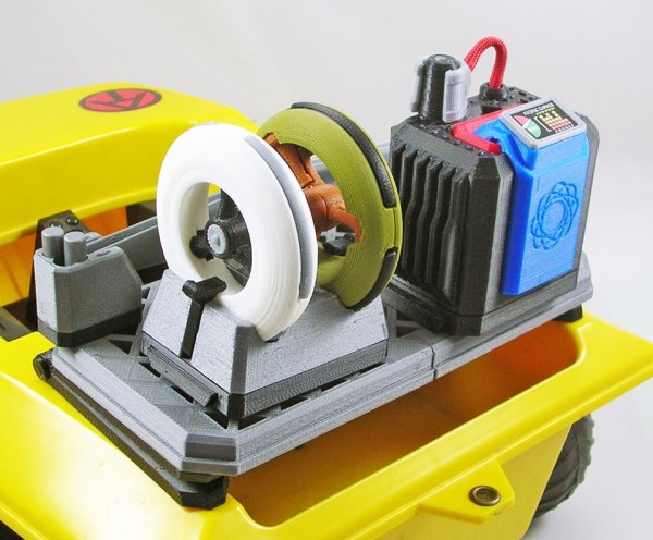
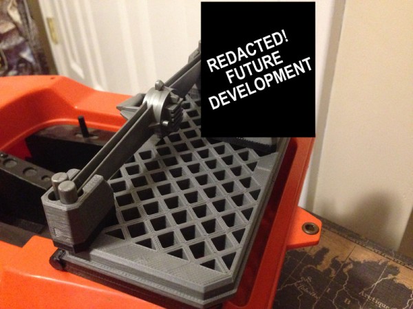
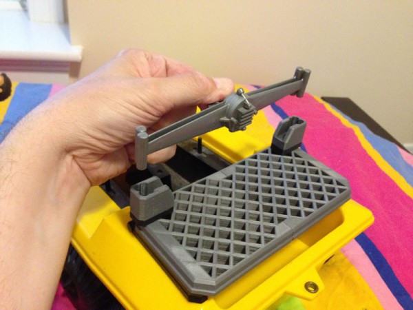
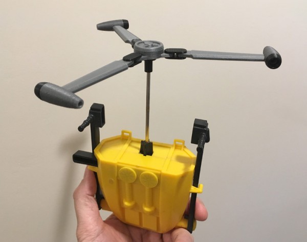
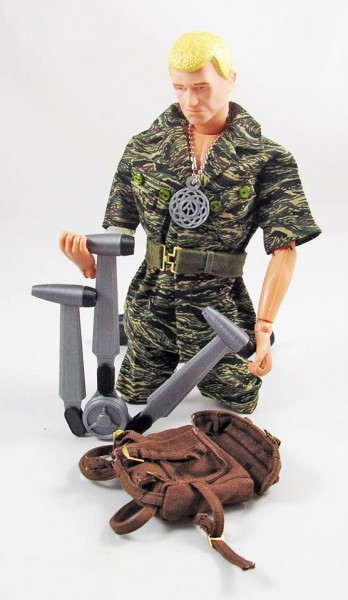
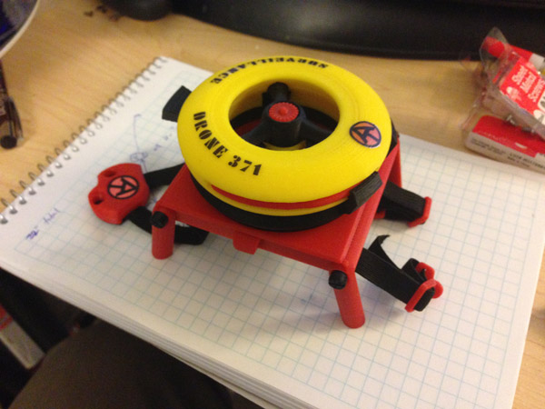
This is the first picture of my RACCS platform with all currently available components attached:
Hinges and Atomic Man Blade Holder;
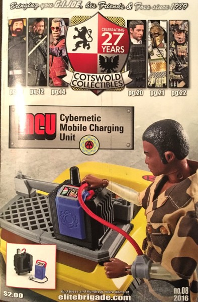
Mobile Charging Unit;
Dual Spy Probe Carrier System
This is the first picture of my RACCS platform with all currently available components attached:
Hinges and Atomic Man Blade Holder;
Mobile Charging Unit;
Dual Spy Probe Carrier System
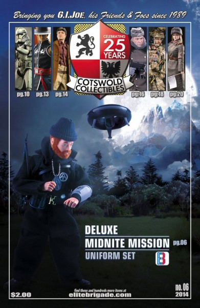
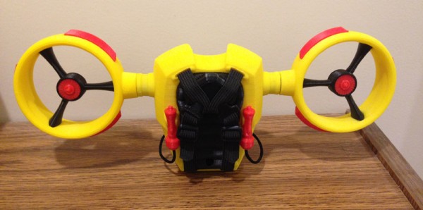
My latest project with Cotswold Collectibles: RACCS Spy Probe Dual Carrier System.
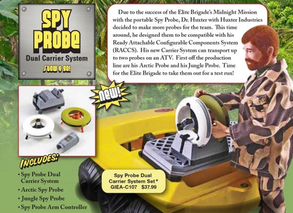
This one reprises the Surveillance Probe I designed for Cotswold as my first project with them: Deluxe Midnite Mission set.
This time Greg asked for a military colored drone for the new military-themed Cybernetic Explorers and other new outfits he was planning. Add to that an arctic rendition, both dockable to a new RACCS Component: The Dual Carrier System.
These spy probes fit two to a unit, and they snap beautifully in place with snap tabs.
The control cuff I designed is slightly different than the one pictured.
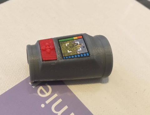
The actual cuff has a separate joystick pad, and screen. The screen is one of my designs as well.
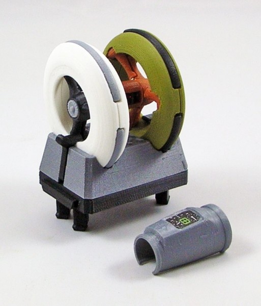
The set consists of the Dual Carriage Unit, which snaps to the RACCS platform, one Military drone, one Arctic drone, and one control cuff. (Pictured incorrectly here. See above.)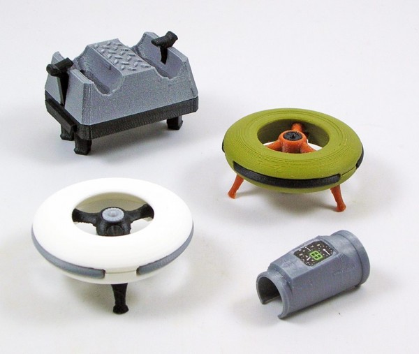
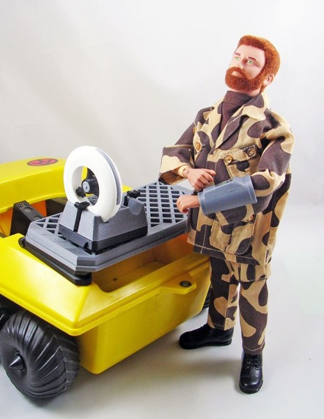
Here the two drones are in place on the unit, snapped in.
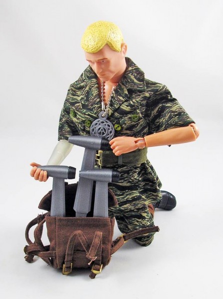
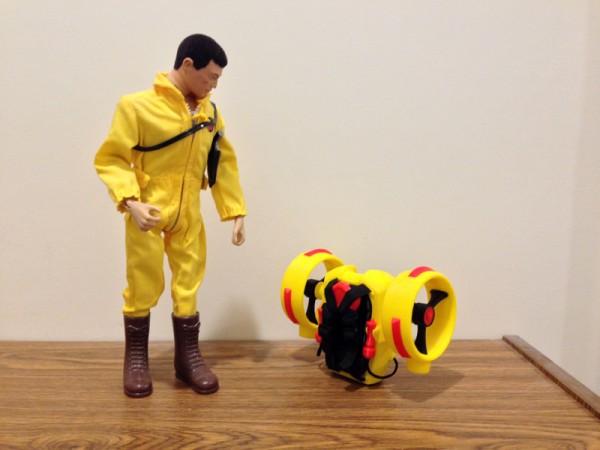
Here, Joe prepares to deploy the military drone.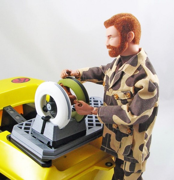
He sets it up on the RACCS for launch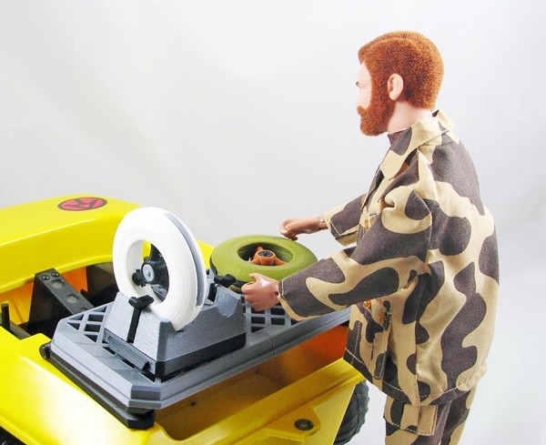
And with a touch, the drone’s anti-gravity repulsors rev up.
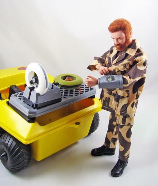
And it is away!
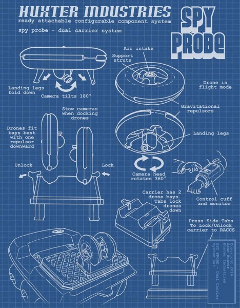
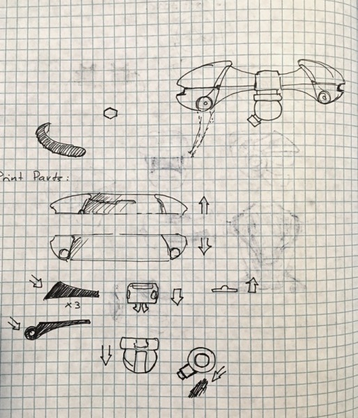
BLUEPRINT
Again, I created a blueprint/instruction sheet for this set:
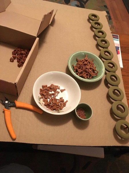
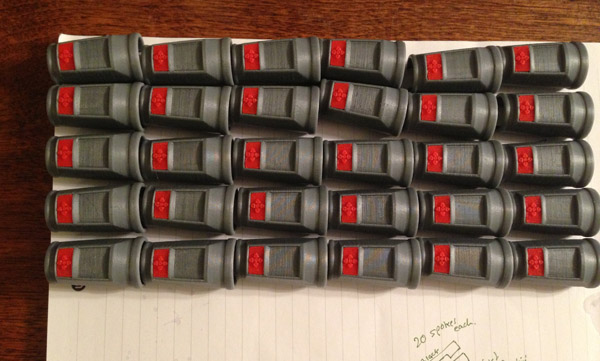
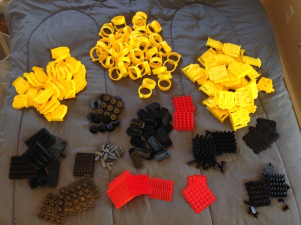
Here you can see a number of the parts that made up the drones, before cleanup. Just as they appear coming off the 3D printers.
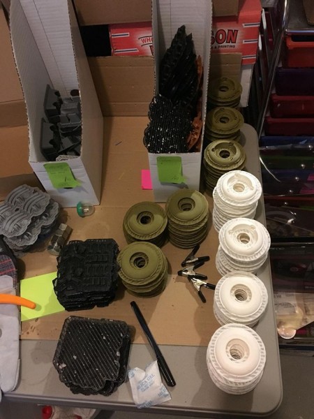
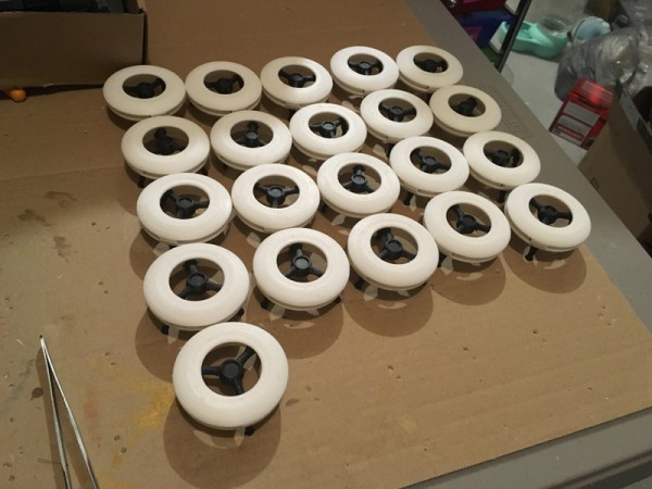
After some cleanup and construction, the military drones are under way:
Greg Brown and I usually communicate by text message. One day he texted me and said he had had this idea for something along the lines of the vintage GI Joe Trouble Shooter. Only this would be a flat platform that covered the cargo bay of the vintage Adventure Team Vehicle, or Trouble Shooter. Something like my Helijet rack but more versatile, more flexible.
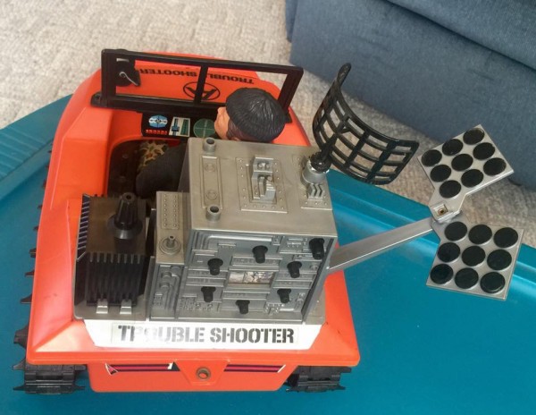
He said he envisioned something like the Trouble Shooter radio/radar pack which was this massive wonderful toy that slotted into the slots of the ATV. Only this would be modular, and allow various equipment modules to be snapped to the rack.
Immediately images came to mind. I sketched up something that spanned the cargo bay’s top area, and snapped in using the holes in the ATV.
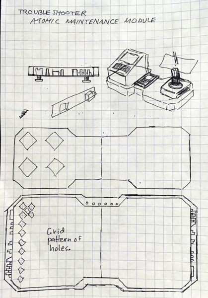
But it had to be able to have multiple various modules connected to it. So I skteched up a grid design figuring I’d connect modules using square pegs. Modules could be slotted onto the platform, as many as would fit, completely configurable by the user.
Greg looked at the sketch I sent and declared I was reading his mind. (He has said this on more than one occasion as he pitched design ideas my way.)
I test-printed a version of the platform (which we still had not named) and it slotted nicely to the ATV.
Then Greg asked if it could tilt up like a car trunk. Immediately I started sketching an idea for a hinge that would fit between the ATV and the platform seamlessly. It just might work!
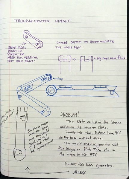
Here’s where the rapid prototyping made possible by 3D printing comes in very handy – when I slotted the hinges to the ATV and then the platform to the hinges, any forward movement of the platform would cause it or the hinges to slip forward.
I was flumoxed. How was I going to prevent this kind of slippage.
Well, thought I. What if I rotated the slots on one part of the hinges sideways? That way the platform would not be able to be pushed forward on the hinges. And the hinges themselves fitted pretty tightly to the ATV.
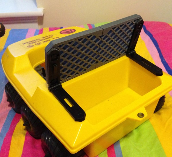
The result was that you had to snap the hinges onto the platform by rotating them a bit, but once locked on, and the hinges attached to an ATV, that platform wasn’t slipping anywhere!
And so the platform was nearly perfected.
But I had a problem: my printer has a build volume of about 13.5cm x 13.5cm x 13.5cm. A 5 inch cube. The ATV’s cargo hold is wider than that. The platform would have to be printed in two pieces.
Immediately my symmetry-loving brain saw a way to make this platform work with two identical halves which snapped together. I was incredibly excited!
So I created a tab and slot for the platform which allowed for two identical parts to fit together perfectly, and still slot onto the ATV like normal.
Huge win!
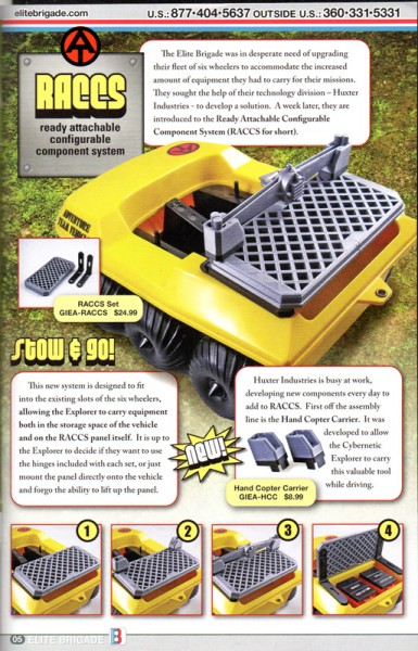
Greg coined the term RACCS which is an acronym for “Ready Attachable Configurable Component System”.
This whole design process was going down around the release of the GI Joe Collector Club’s new freebie figure, a modern retake on Mike Power, Atomic Man. A new head sculpt on a vintage body with one arm and both legs made of clear plastic.
It also coincided with the re-emphasis of Cotswold’s own Cybernetic Explorers, figures made on repro vintage bodies, with various combinations of arms and legs molded in clear, which was getting some attention, and had its own outfit sets already developed.
This was a very popular figure, and club members couldn’t wait to get their hands on the new Mike Power.
The vintage Mike Power came with a two piece copter blade set that Mike held in his Kung Fu Grip, and a small wheel on his forearm let kids rotate that hand easily, so Mike Power could simply spin his hand and be a helicopter.
Greg noted that many collectors had these, and many would love to have them stored in a module made by me for this new platform design. So I created a two piece module pair that connected to the RACCS and the Atomic Man’s blade could fit snugly in place, carried by an ATV.
I also created a blueprint/instruction sheet for the RACCS platform, with reference to the blade holding module.

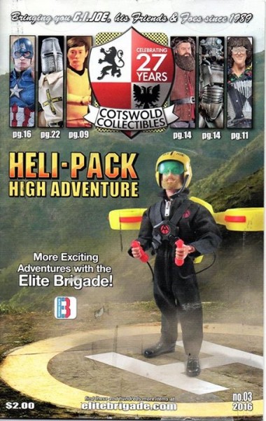
And so RACCS was introduced in the sixth catalog in 2016:

By the time RACCS was announced in the catalog, Greg and I had already brainstormed a bunch of modular units that would fit on the platform, so you could configure your own adventure.
The next one up was to be a Mobile Charging Unit so Mike Power or the Cybernetic Explorers could charge their bionics while on a mission.
I started sketching.
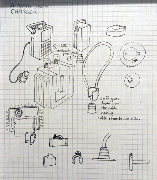
First thing I came up with was a box with ridges which would resemble heat sink blades to cool the atomic charging unit. Greg wanted a removable box the Explorer could take with him in case he needed an emergency charge, a box with a handle and its own charging coupler.
No problem. You can see the genesis of the idea in that sketch.
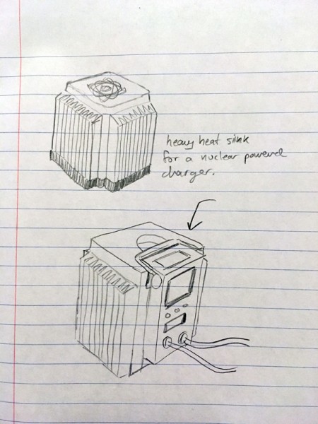
Which then got updated until I drew this:
I ended up with a charging box which looked a bit like some of the parts of the original Trouble Shooter, which was no bad thing.
Even the nub I created for the cuff to store on resembled the Trouble Shooter module.
Then I modeled up and printed up a prototype.
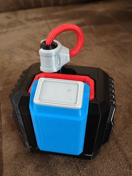
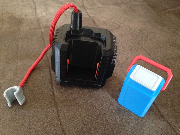

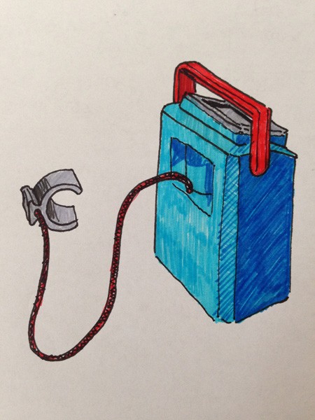
I found some red paracord to act as the main cable to the larger arm cuff. This would be a fast complete charger, charging up Mike’s bionics to full.
The smaller blue box (with the Cybernetic Explorer Atomic Logo on it) has a tilting handle, and a clip on the main box to hold it in place. Pull up and on the back is a cavity to store a smaller arm cuff, connected by a smaller, black cable.
Both of the cables store inside their boxes.
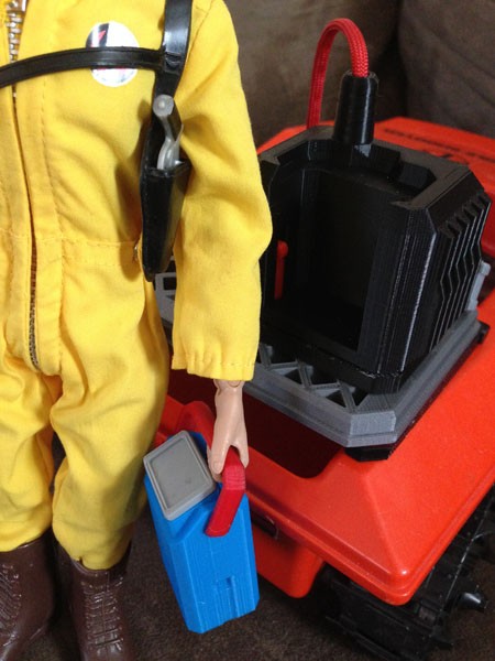
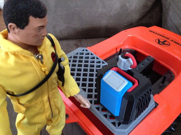
Originally the clips for the MCU would friction-fit into the RACCS slots like the Blade Holder units do. But while the blade holders are smaller and the pegs clustered closer together for a good friction fit, the MCU could not rely on friction. So I created a unique new spring-loaded clip system that worked easily with the original design. I simply created a slot in the bottom of the unit, slid the clip-spring part in, and a single screw connected it all together. The flexibility of the plastic itself allows for enough spring action for the module to clip nicely to RACCS and then remove again by pinching two tabs on the side.
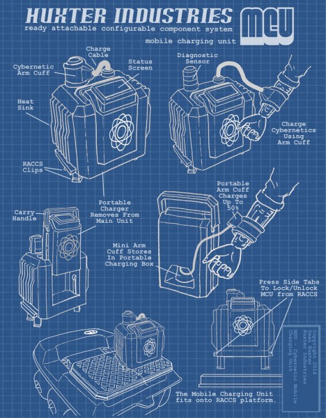
I also came up with a blueprint for these.
The catalog came out recently, and these items were made available for pre-order, with delivery in November.

But what’s this?
Another item?
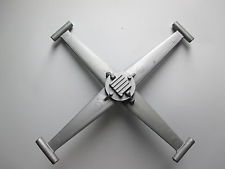
Greg asked me long before the Charging Unit to come up with a replacement blade for Mike Power and the Cybernetic Explorers to replace the blade that came with Mike, since a lot of owners of vintage Mikes may not have the blades. They tend to get lost.
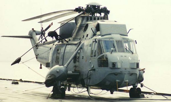
But he wanted the helicopter blades to be able to fold back like an aircraft-carrier helicopter.
It turns out this was a hard challenge.
I could make the blades hinge, but 3D printing them consistently would be something I didn’t think I could guarantee.
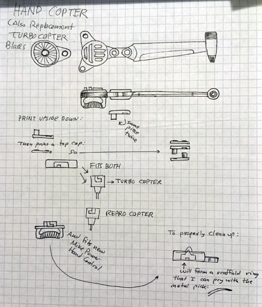
As you can see by the sketch, the hinge plates have to be symmetrical and fit together while snugly fitting into both the hub and each blade. If this was too snug, it would not move. Too loose, and it would not stay in place. It was tough. But I think I did it.
As a further benefit, I didn’t just fit a handle onto it that resembled Mike Power’s blade. Rather, I made that handle lock into the hub. Why?
As a sneaky extra feature, I made the hub compatible with vintage Turbo Copters!!
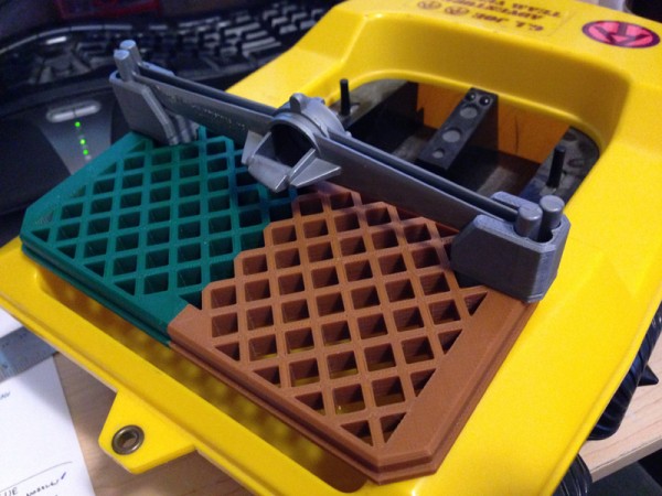
Here is a pic of an original Mike Power blade, along with my Tri Copter Blade, next to an original vintage Turbo Copter blade.
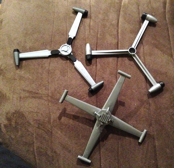
(Don’t worry. The Turbo Copter blade is turned upside down to show the hub opening. The turbo heads are facing the right direction on mine. (I hope.))
Fully extended: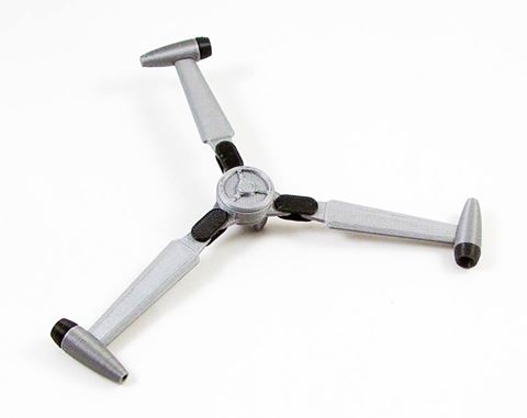
Cybernetic Explorer operating the blades, getting ready to take off: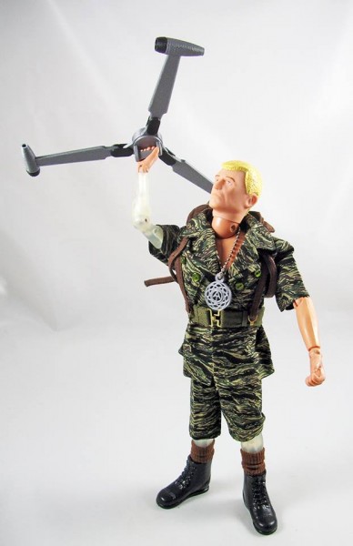
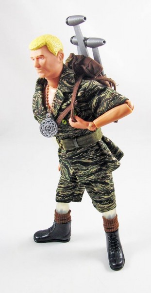
Stowing in backpack:
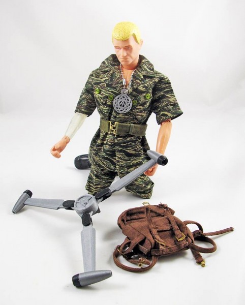
Folding blades:
Stowing
:
And going:
Seen here, attached to vintage Turbo Copter. It is designed to fit the black, yellow, green (Action Man) Turbo Copters. The more recent Hasbro reproduction (a lovely thing) will not fit, as the coupling is different, and rotates the wrong way.
RACCS Spy Probe Dual Carriage System
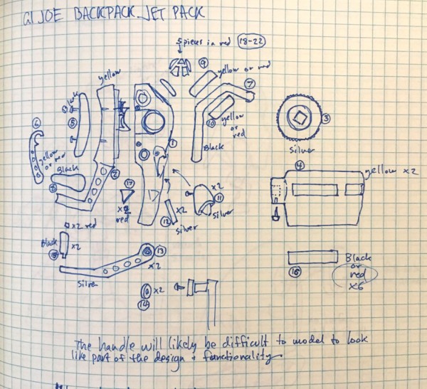
As reported before, I went to the Dallas GI Joe Convention in 2014. I had brought some of my 3D printed GI Joe stuff with me, including my two dioramas for the show, the GI Joe Action Pack Jetpack on a custom AT Launch Tower:
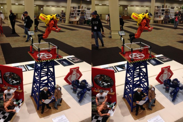
(cross-eye stereo image)
And the Search for the Endangered Pygmy Rhino set, which included a number of 3D printed items including a tranquilizer bazooka, an aerial drone and its backpack, a laser cutter to remove a rhino’s horn, an electronic prosthetic surveillance horn, and a sealant gun to affix it.
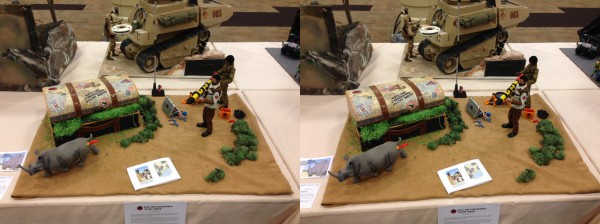
(cross-eye stereo image)
While there I found Greg Brown at the Cotswold booth, where I bought a cool set they had made featuring a black puma and outfit. I also had on-hand some samples to show him, and he took a few minutes to look at what I had brought, while he was dealing with other customers and some issues with the online billing software.
He seemed excited with the jetpack especially, and we chatted for a bit, and parted company. I had a great convention, my second, and first traveling, we did the parachute drop, including a later clandestine drop, I got to meet up with the Regular Joes and have dinner out, walking past the Book Repository, Kennedy’s assassination site and his memorial there.
It was some time later when I was back home that Greg approached me with some ideas for Cotswold Collectibles.
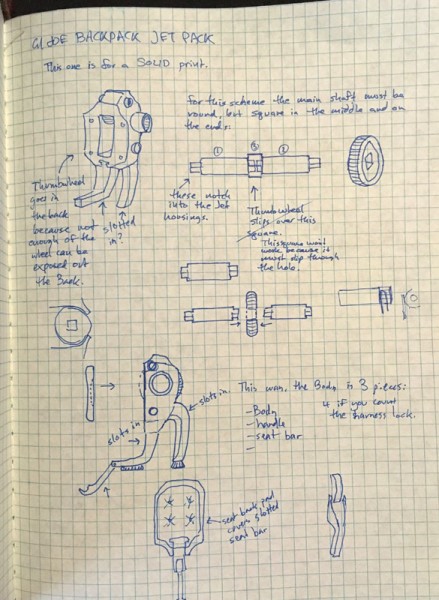
First up, he wanted to distribute the jetpack. From previous writings on the subject, I felt that the jetpack needed some serious redesign if it were to be strong enough to sell. I would hate to sell something that was easily breakable, and I knew my current design was very delicate in how the harness connected to the body. 3D printing can be strong in layers, but not so much in tall thin cylinders. The layers break easily like a twig, but there are definite ways to make very strong things.
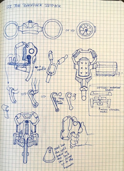
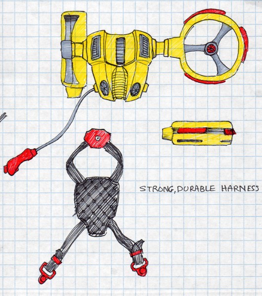
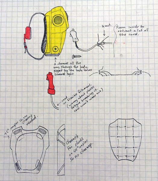
Here are some early concept ideas:
So I went back to the drawing board with that project.
Meanwhile Greg brought up my surveillance drone. Seems he wanted to do a special outfit set that included these new cloth backpacks they had made, and wanted some things to go in them. The first thought was to 3D print some of my cool aerial drones, but smaller.
My original was too big to fit into the backpack.
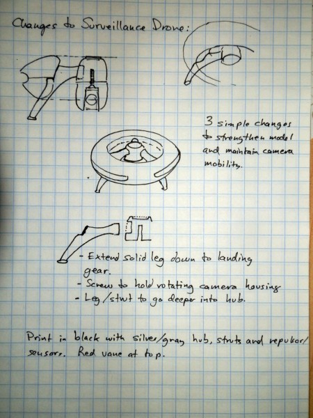
But the design was very cool. The one issue I had (being very nervous about breakage and ease of assembly), was to consolidate the hub and top struts into a single piece which would be very strong.
But you can see below that I still had not yet come up with a good landing leg system, even though the rest of the drone was basically fully fleshed-out.
I continued hammering away on concept sketches:
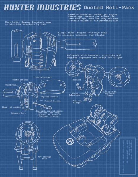
Mostly, it was beginning around the basic design of the jetpack engine housing, a Dyson-like central hub forcing air through a hollow body, downward in a stable air column for lift. Even the hub and struts were nearly identical.
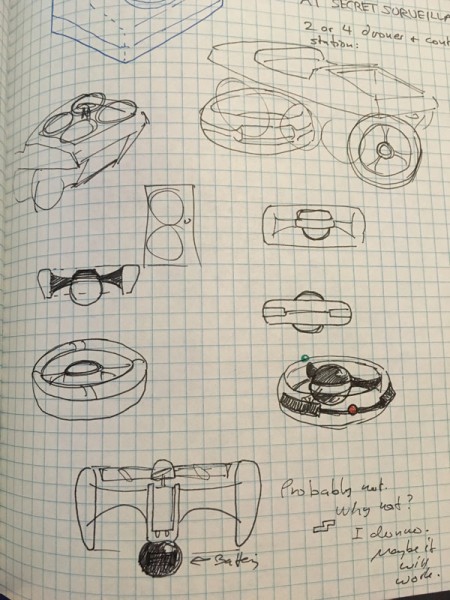
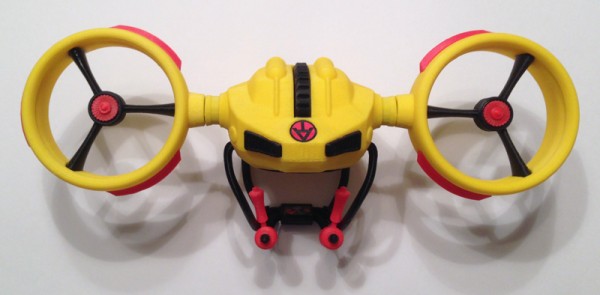
I decided I wanted fold-away landing legs.

That’s when I discovered I could split the strut and make the lower half a landing leg that hinges down!
I could retain the incredibly cool leg system I created where I split a nicely sculpted strut right down the middle so that half of it hinged down as landing legs. I could retain the camera, which has a 360 degree range of rotation along with a pivot that allowed the camera to see a full hemisphere below the drone. (Play of course. No real camera… duh)
This entry talks about how I was able to scale them down, and found, much to my surprise that even at 50% of the original size, I didn’t have to make any changes to the model and it still worked as intended.

I think it was the first step down that actually fit into the packpack:
So not long after that, the Deluxe Midnite Mission set was introduced, which included the black drone as well as an arm cuff which acted as the remote control and monitor for the drone. These both fitted onto the cloth backpack very nicely.
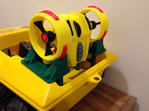
I spent some months in the summer redesigning my jetpack from scratch. I reduced the size of the jet bells, I completely redesigned the body to be more compact, curvier, and less – bulky and awkward. It retained the exact same thumbwheel and mechanism for tilting the rotor housings, which were still based on the Dyson fan design – a jet engine forcing air into hollow housings, out an aperture cut into the interior of the bell, down the aerodynamically curved housings, and straight down into a stable column of forced air. But much more powerful.
The harness was the hard part, since the original was 3D printed and so easy to break I had to be very careful mounting it on a Joe and taking it off.
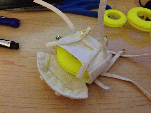
So I went back to how the original vintage GI Joe rocketpacks and other items were made. A lot of those used elastic strapping with clips as harnesses. The one thing I wished to avoid was sewing. To connect two pieces of elastic strapping I’d need to sew them together. I could do that for a prototype, but I couldn’t imagine doing it for a larger run of, say, 30.
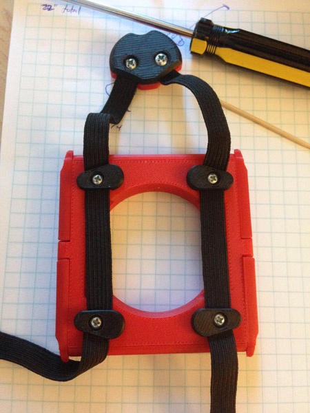
So I came up with a way to do the harness as a single loop of strapping that began and ended in an angled dart, which I could then cauterize with heat to ensure it didn’t fray at the ends.
I hate bragging (too late!) but I came up with a very clever and intricate way to feed a length of elastic strapping into the jetpack body, onto a harness connector, then folded back onto itself and back into the body, so that the two loose ends hung down freely so strap adjusters and clips could be attached easily. Again. No sewing required.
The trick was folding it in the middle and connecting it to the chest piece with two small screws which did double duty as holding the two halves of the chest piece together, and also holding the strapping in place by having the screws screw into the straps.
I invented the method for the Aerial Drone Backpack.
Likewise, inside the body, the straps were clamped to the inner body by the seat cushion, both of which had ridges printed onto them to hold the strapping in place, and then two of the screws went into the strapping to secure that hold.
This worked like a charm! And the 3D printed strap adjusters allowed the user to fit the harness onto just about any size body.
The next thing I struggled with was the control handles. My original had them on rigid arms that swung down so Joe could hold the twin joysticks. But I had seen real jetpacks designed without rigid arms, and even the GI Joe Collectors’ Club Convention Set “Search for the Sasquatch” had a very cool repro jetpack with two cables attached to two small hand-grips. That was the answer to my final fragility question.
I would attach two hand-grips to cables, non-rigid.
Then with that in mind I could do a few new cool things, like snap the joysticks to the body itself, and then allow the cables to retract into a hollow area inside the body of the jetpack for very compact storage.
The engine housings would still snap off and snap back onto the shoulder clips just like before, but before the clips were printed vertically like the cylinders they were attached to, which meant they were inherently breakable. Printing those sideways strenghtened the clips, but I wouldn’t want to print the cylinders sideways. So I printed them separately, and glued them together. Strong!
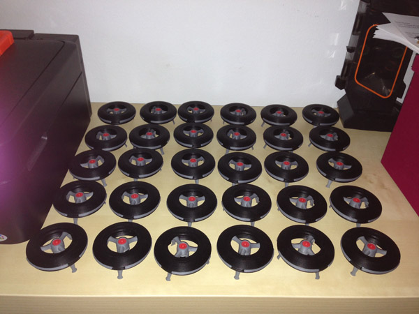
When I had made all of these changes, I was confident I could sell them without much fear of breakage. So I agreed to deliver 30 of them.
Yikes! What was I thinking???
Printing just one half of the jetpack body required 8 hours of printing. The other half took about 6, and that didn’t include the housing bells (2 each) the cushion, the thumbwheel and cylinders, the clips, the harness pieces, the jet intak embellishments… this was going to take a while.
With two printers I could do the job in a couple of months, probably. But of course at that point one of the printers failed and I had to send it in for repairs, so I was down to one printer churning out 30 jetpacks, each of which had 30 parts.
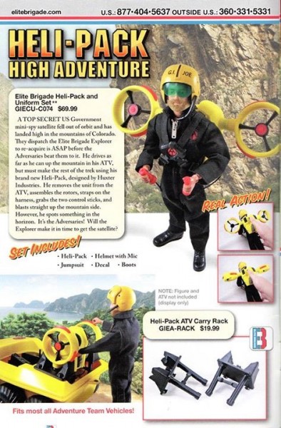
And I also had to print 30 ATV racks which slot nicely into the cargo bay of a vintage GI Joe Adventure Team Vehicle (or Trouble Shooter) so the jetpack could be carried by an ATV easily.
Whew. I was wondering if I had done something very stupid.
But when I finally got 30 of these babies printed, assembled, tested and ready to send, I was very happy with how it all went.
But I couldn’t stop there either. I decided to make a blueprint/instruction sheet for it.
I used the money I made to buy a third printer so future orders could be done far faster.
(In case anyone should think I’m in this for the money, the design time alone would be worth 10 times what I charge for these things. I charge just enough to cover material costs with a bit extra so I can buy new stuff for the hobby. Also, things like screws, elastics, paracord, etc, I also have to buy, experiment with, toss out, get different versions, etc. This is just my hobby. When it stops being fun, I will stop doing it. Until then, look for more designs from me.)