Space 1999 Moon Buggy First Real Print

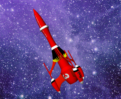
The 1970s Gerry Anderson TV series Space 1999 was iconic. I thoroughly enjoyed it, and it enjoys huge fan admiration throughout the world to this day. I wanted to be able to make a fairly accurate model of the Moon Buggy used in the series which was a barely modified Amphicat, a six-wheeled ATV readily available in the early 1970s.moon-buggy-publicity-shot

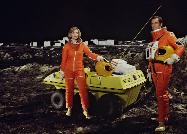
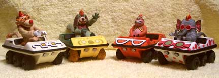
These were fairly popular in the 1970s. In fact another well-known (at the time) TV show featured them: The Banana Splits.

banana-splits

GI Joe even had a couple, but heavily modified by Hasbro. There was the GI Joe Adventure Team ATV used in several of the cooler toy sets:mummys_tomb_catalog_photo

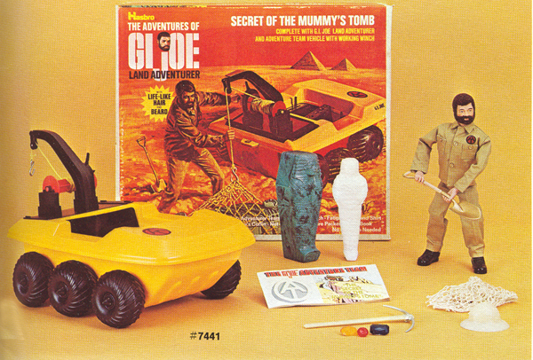
Irwin also made one to scale with the GI Joe line, which was much more accurate to the real Amphicat, though not totally accurate:

amphi-cat-irwin

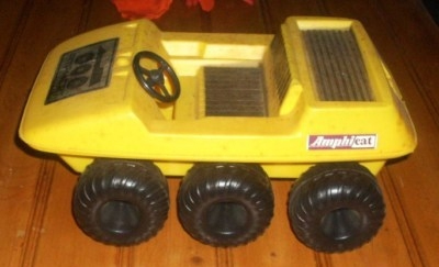
In fact, I even found one in my grandmother’s home town in Newfoundland, parked near the house she grew up in:

amphicat-2-large

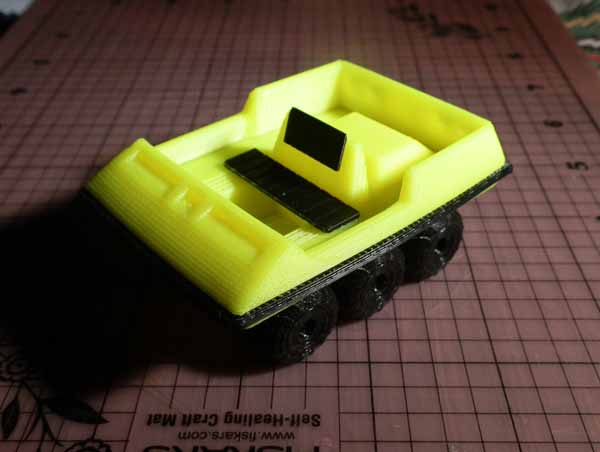
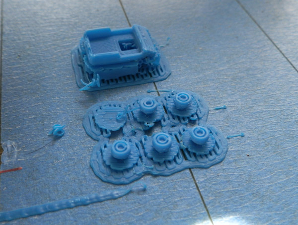
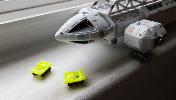
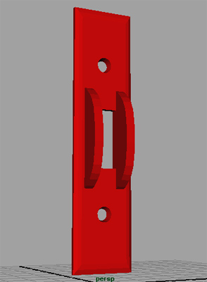
So I decided to model one, using photographic images as my best reference. Here’s where I am now:

amphicat-model-seats-added

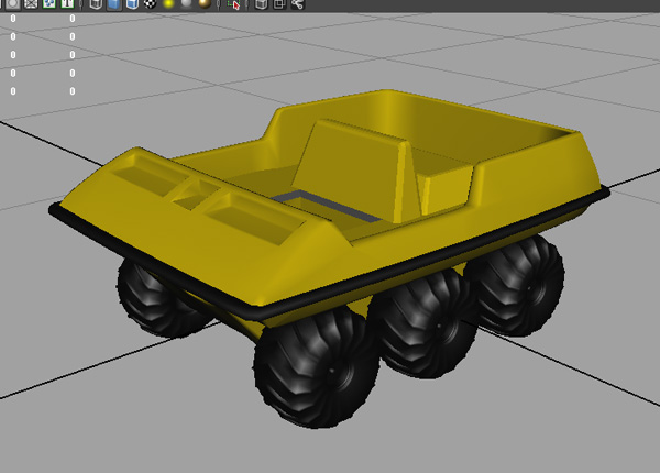
The model as it currently appears here has nine parts. Each wheel is its own piece, eventually to have a metal axle, so each wheel pair can rotate, the bottom section, the upper section and the black bumper trim.

I modeled it solid, but I had to split it for better printing, and to fit the trim in if I wanted the trim to be printed in a different color.

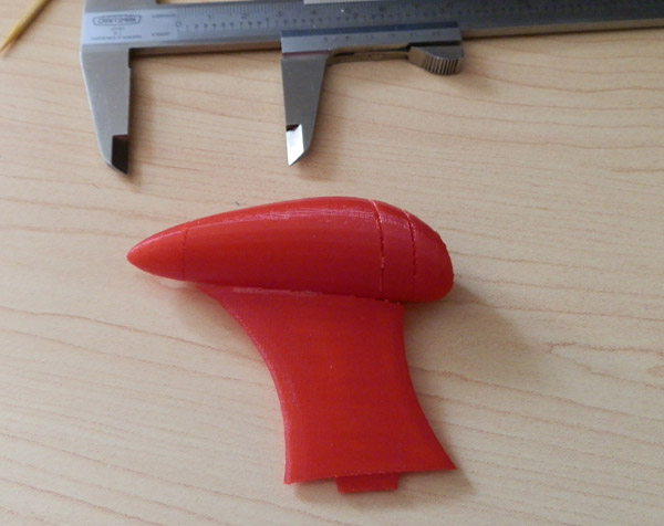
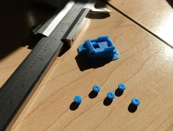
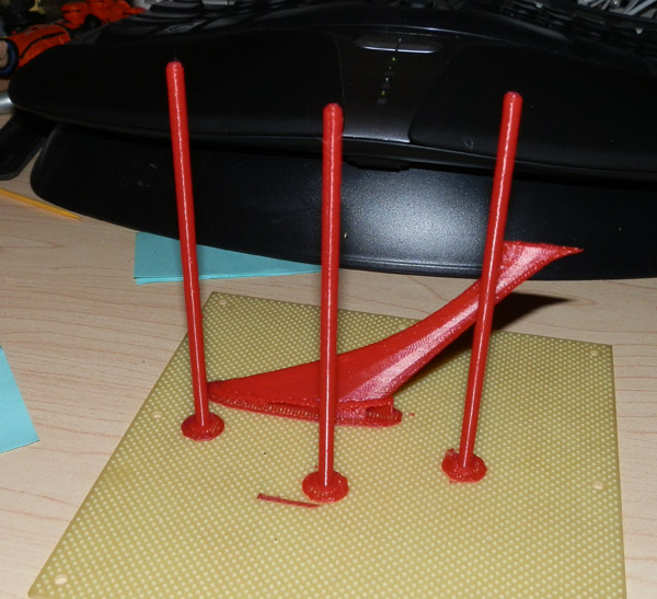
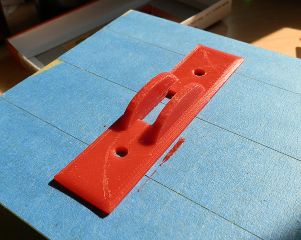
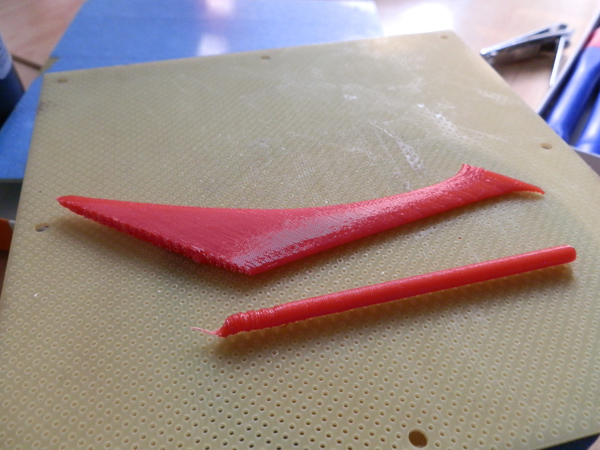
So today I test-printed it at about three inches in length to see how the pieces would fit.

To cut it up I dissected the model at the trim line where the model forms an edge. However, the interior of the vehicle’s flat surfaces are actually lower than this cut, so I had to make some adjustments and make the slice across the body pyramidal, rather than perfectly flat.

This left a very thin floor to the top section of the vehicle, but I wanted that to be a solid piece, with floor, to smooth the transition to the inside wall of the vehicle.

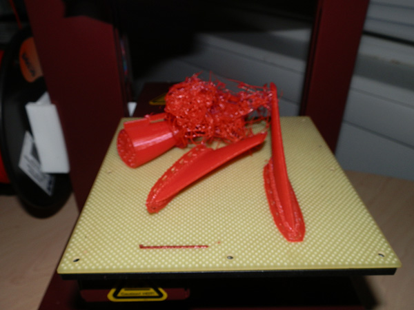
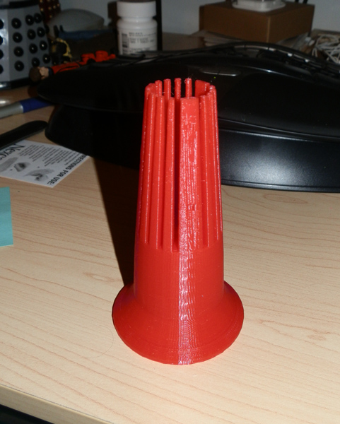
But when I lifted the top section off the rafting (the layer of plastic the printer lays down first to ensure a good print) it couldn’t distinguish between raft and floor and the floor was far too thin.

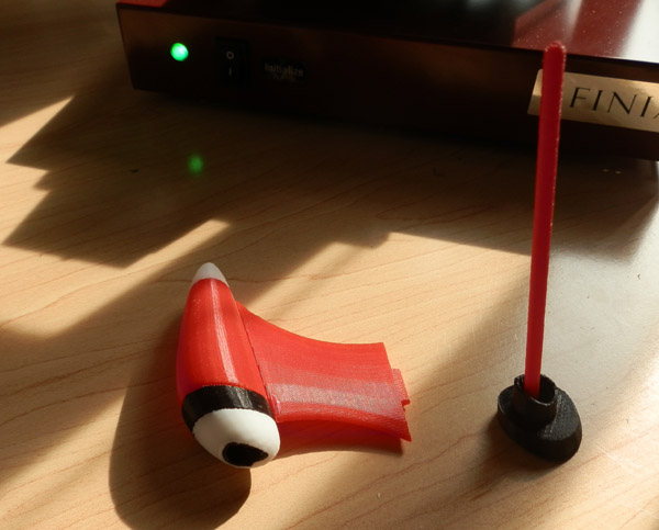
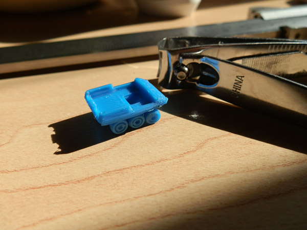
This happened: (Well, after I did some trimming)

OLYMPUS DIGITAL CAMERA

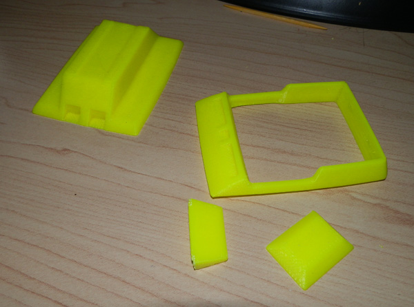
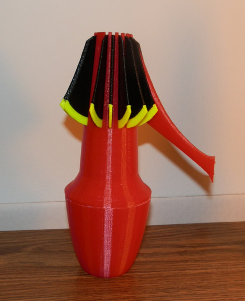
I cut the seat and engine housing off because what was left of the floor it was on was not there… but by coincidence or design the top still fits nicely on the bottom piece, as if the floor on the bottom piece (supposedly a gluing surface) actually works ok as the actual interior floor of the Amphicat. I may have to redesign the thing to have a thicker floor, but even that may not work. I may take advange of the good fit and just print the top half without floor, and put the floor as the topmost layer of the bottom half.

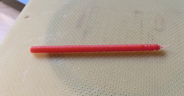
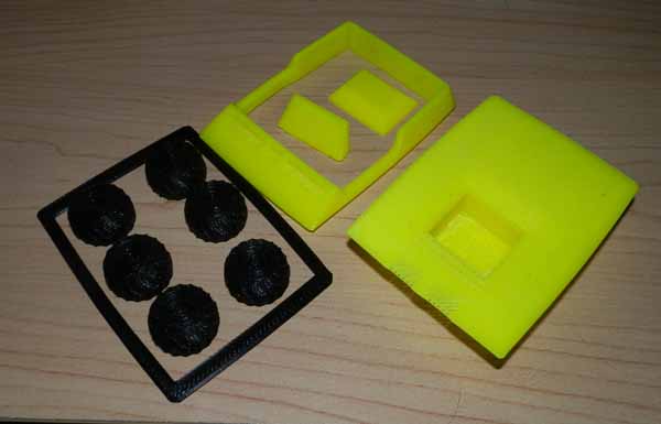
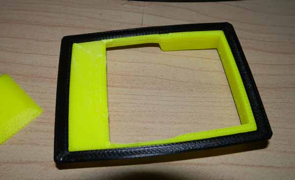
The trim sandwiches nicely (hopefully) in between the two parts, which have a gap when put together just the right shape for the trim to fit in.

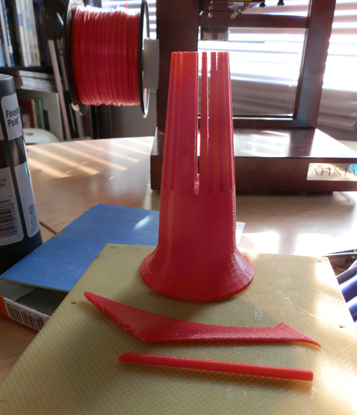
I am currently printing the trim and wheels.

OLYMPUS DIGITAL CAMERA

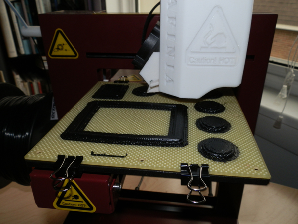
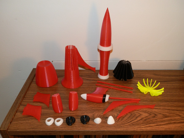
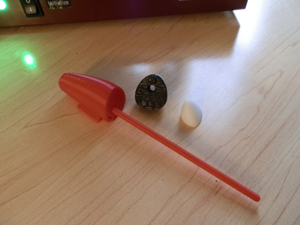
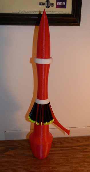
Here are all the parts that I have modeled up until now. There are some small parts coming, in fact the seat cushions are currently on the printer, being printed.

OLYMPUS DIGITAL CAMERA

Here is the trim, snapped onto the body, being glued in place:

OLYMPUS DIGITAL CAMERA

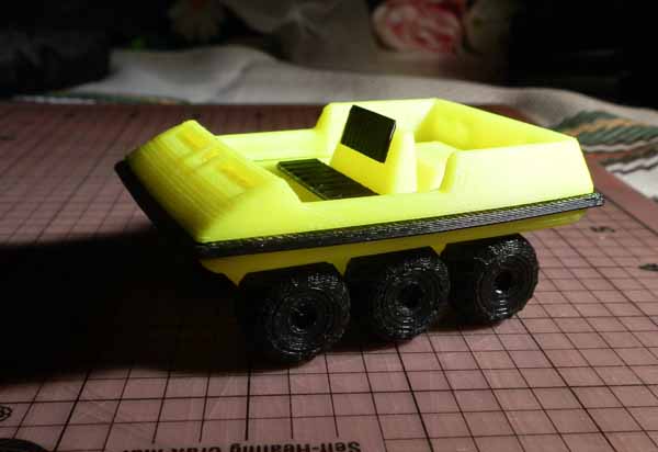
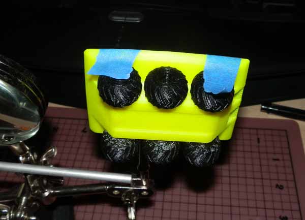
And here, the wheels are being glued on. As I said, I will be making axles, but for now, I’m just gluing them on to see what they will look like.

OLYMPUS DIGITAL CAMERA

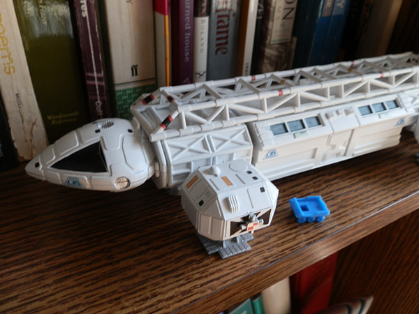
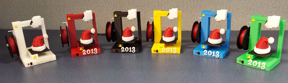
And, at least for now, this is the final print. The yellow is hideous, and the black very shiny, but not bad for a 3″ version.

OLYMPUS DIGITAL CAMERA

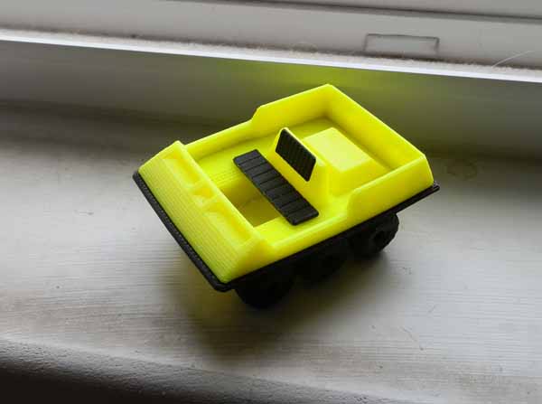
Update: I took a few more snaps in somewhat better lighting conditions:

OLYMPUS DIGITAL CAMERA OLYMPUS DIGITAL CAMERA

TB3 Rocket – First Build Under Way

So after the weirdnesses with printing some of these parts (and learning some good lessons) I now have this:

OLYMPUS DIGITAL CAMERA

These are all the parts ready to glue together. (Note, for V1.0, this rocket has some tiny tabs and slots in places, but they are for guidance only at this point. Later, I will make them so they slot together much better, and that will align them, hopefully. For now, I’m using Superglue and masking tape to hold the alignment until the glue hardens.

I anticipate some ill-fitting because gluing of parts can be a bit arbitrary, and a tiny bit of a degree off can cause some misalignment. The aforementioned better slotting should take care of that in V2.0, which I probably won’t work on until later in the summer.

Troubles Printing

Last night I printed six things on the printer in a single print. This isn’t a bad idea. But as an experiment I printed them on the blue masking tape. These would be tall objects, or at least two of them are very tall, but four were moderate, and they had all printed before without issue.

Last night, however, when two items had finished (the shortest) and the two medium items were five layers from completion, the print head knocked one over into the other, ruining the print.

Tonight I printed the four spoiled items again. And though I used the bare perf board, the engine pieces knocked over again!

I’m not sure why. These are items that, as I have said, printed fine before. Perhaps it’s the fact that I’m printing multiple items. I’m now going to attempt to print them individually, because these are the last four parts I need for my rocket v1.0 to be fully ready to assemble.

Here’s an image of what I got when I got back to the room, and shut the print down:

OLYMPUS DIGITAL CAMERA

My New Commodore 64

At the stage of development we are now, home 3D printers are what I like to equate to a Commodore 64. The tech is awesome, and we can extrapolate that in a decade it will be so much more awesome. But for now, my tinkering feels just like it did when I was exploring the possibilities of my C64 back in the mid 1980s. It was an exciting time, and what I learned on that computer I took with me and made a career and a life out of.

I began calling my Afinia my new Commodore 64 because it brings back all that excitement and possibility. I haven’t felt this giddy about new technology since those days of the C64 purchase.

So I’m modeling a Commodore logo to stick to the Afinia printer (under the bed where it will be out of the way.) It will be tacked in place, nothing permanent…

This is the logo:

Commodore Logo copy

Here it is, extruded and beveled, and printed in three colors: Black for a base to sit it on (and align it), blue for two pieces, and red for one.

OLYMPUS DIGITAL CAMERA

Here, glued in place:OLYMPUS DIGITAL CAMERA


TB3 Rocket Project: The Engines

As you can see in the 3D model, the engines have multiple colors. (Though the number 3 will not be modeled.)

tb3-concept-test-render-500

I am printing those in color, not painting them, so I had to cut up the model yet make sure they fit together. Last night I cut them it up so it would fit into the main fin, as well as fit together.

It is not obvious from this rendering, but at the top of the engine is a black intake, a funnel into which the antenna struts go. I have not yet modeled the cylindrical hole to make those fit. I concentrated on making the pieces fit together.

The tricky one was the white top, as it had to act as a cap on a peg that would be both the black stripe and the rocket intake funnel.

OLYMPUS DIGITAL CAMERA

Normally I print in the color the part will end up in, but for a quick test fit I just used the red color, so I wouldn’t have to change out the color 3 times, which is a bit time consuming.

These pieces do not yet have pegs to slot them together where they join, so I just SuperGlued them for now. (The final model will also require glue. I’m not making the connections that perfect.)

And here you have the result:

OLYMPUS DIGITAL CAMERA

These are printed at .25mm. The final will be .15mm, so the connections between the pieces may be better. But when you print on an angle, you get stepping, and when you have two pieces that have stepping that are supposed to fit together, you hope for the best. With .15mm, the fit should be better than you see here.

Next: Drill a hole down through the engine parts that will fit the engine struts, and redesign the bottom piece to have a rocket cone. Right now it is round, and not a realistic engine. In the concept, that round bottom irised open to reveal a rocket exhaust. My finished model will just have a flat bottom with a cone in black (another snap-fit part I have yet to model.)

Update:

Last night I printed the pieces in color for a new test-fit. Then I began the process of drilling holes into the pieces to fit the antenna struts. This photo shows the engine assembled in color, (without the hole for the strut) and next to it, the top piece (which has the jet intake and the black stripe) with a hole drilled and the antenna strut test-fitted in it.

OLYMPUS DIGITAL CAMERA

Next up: Drill a hole in the main body and redesign the slot for the main fin. I didn’t like the way the main fin fit up against the engine housing. Resolution at this level isn’t sufficient to make those pieces fit perfectly, so I’m going to make a slot in the engine for the entire fin connection to fit inside, just a bit, and then I have to redesign the bottom section of the body to do the same. Since that would require reprinting of both the bottom and mid body pieces, I may not do that yet.

But the white bottom piece has to change a bit too, to cut a maneuvering thruster hole there. I am also adding the real rocket engines to the dent in the bottom piece. (Originally the three engines were going to be sufficient, but with small thruster outlets, it made little sense that that could power this rocket. So instead I’m using the bottom divot to install three massive rocket engines. More on that as it develops.

Update 2:

Last night I added tabs and slots to each engine piece so they could slot together nicely for gluing with perfect alignment. The main engine body and the black stripe piece now have holes in them for the engine struts, and they fit perfectly. I redesigned the main fin slot to have a tent roof, rather than flat, because a flat roof requires support material, and a tented one does not. No visible difference, as it’s inside the part.

Here are the pieces, now complete, for this test model:

OLYMPUS DIGITAL CAMERA

My next task is to print two more of this, and two more main fins and upper fins, and I can actually fully assemble my rocket as it is now, before I begin adding detail like thrusters and the like.

Space:1999 Moonbuggy Project

This whole 3D printing thing started with me wanting to print a Space:1999 Moonbuggy. I had just customized a 3.5″ Moon Buggy variant using a toy 8-wheel ATV I found on eBay. I painted it, printed custom decals, and the result is quite nice.

OLYMPUS DIGITAL CAMERA

But it’s just a derivative variant. I wanted a more accurate one.

So I sent a test model I found online, not a very accurately modeled one, and the model wasn’t water-tight, and just not optimized for 3D printing, but the result wasn’t bad.

So now I’m printing a 1.75cm version of a model that I am working on from scratch, (in blue, because my Premium Yellow was back-ordered) to see how it scales with my Product Enterprise Eagle. The model is not finished yet, nor is it optimized to print so small.

So far it’s printing the body ok, but the wheels not so much. One seems to have come up off the raft. Oh well, printing at this tiny scale is probably not that recommended. Let’s see what the final result is. Perhaps to print 6 wheels I must print 12 and hope 6 of them come out ok.OLYMPUS DIGITAL CAMERA

Plus, some tiny detail will have to be removed if I intend to print this thing small. The tiny vents at the back, which are supposed to print ok at 4″, cause the back wall to print incorrectly. That’s an easy fix for when I do this again.

OLYMPUS DIGITAL CAMERA

I mean COME ON!!!!

OLYMPUS DIGITAL CAMERA

OLYMPUS DIGITAL CAMERA

Update: Here are two more, printed in yellow and black for better color. (The yellow is a bit hideous. I’ve ordered a yellow that is far more like the original Moon Buggy, but I don’t have it yet.) I remodeled the back just a bit to fix the problem with the rear vents, but apparently it didn’t fully fix the issue. And I included a quick seat and engine cover in the back. The photo probably doesn’t show the detail well because of the sickly-translucent-Hi-Vis yellow…)

OLYMPUS DIGITAL CAMERA

More Rocketeering Today

As you may recall from this post, the antenna struts of my TB3 Rocket gummed up if printed alone, due to the head not giving the plastic time to cool. This post is about how to do it right… and even righter.

And after fitting my curved upper arm onto the body, I thought it a bit thin, a bit flimsy. So I remodeled it by thickening it up a bit. I took the opportunity to print three antenna struts, so the print head would take time to go between them to print them, rather than gumming up the strut as you see in the picture above.

This was the result:

OLYMPUS DIGITAL CAMERA

I did learn something though: Rather than print three, I should print five. When it was printing just the three struts, it kept going back and forth in a sensible way, so it would do A, then B, then C, then C, then B, then A. Only B got a clean cooling break. A and C got two layers in a row, which didn’t seem to harm them at all, but to play it safe next time, I’ll print five, and toss A and E, keeping B, C and D.

Meanwhile, I modeled three slots into the Lower Body piece to accommodate the Main Fins, modeled the Main Fins to fit into those slots, and created the slot that the main engines would eventually fit into, so I could test-print a Main Fin.

The printer is currently printing those pieces.

Meanwhile, here is the result of the reprinted black and yellow vanes, slotted into the body of the rocket:

OLYMPUS DIGITAL CAMERA

The yellow (the cheaper plastic) needs to have some trimming done where the tips meet the black, but that’s easy.

And here it is, assembled, as of today. The only thing missing is the antenna strut which I had no good way to put on for this photo.

OLYMPUS DIGITAL CAMERA

Once the arm, main fin, engine and antenna work, I will print two more and put them on the body, and I’ll basically be done this test print. Then to print one for real, at .15mm. Yikes. That will take some time to print!


Plastic Confetti

Almost immediately after my first print I noticed something about maintenance of the Afinia printer, and any printer that uses perf-boards as a print bed. (Perf-boards are quite good at holding down the part. There are other methods, but this one is tried and true.)

When the raft is pried up off the perf-board, it doesnt’ always come up cleanly. That means that the plastic pegs that have melted down into the holes (which make the part hold firm to the board while printing) have come off and are now stuck in the perf-board holes.

These should be removed before printing again otherwise the benefit of the holes will be diminished.

I use a hard-wood toothpick. The ones that are square for most of the shaft and are sharpened to a non-sharp point. These points are perfect for shoving into the perf holes.

Flip the board upside down and begin pushing the toothpick through any hole that has plastic in it. It’s not always easy. Sometimes those little buggers are stubborn. And the toothpick breaks. You’ll need a lot of these.

(I’m considering finding the right paperclip gauge to use a paper clip instead, and then print a little handle for it. But that’ll be later.)

And so after doing this over my trash bucket about 20 times now, I thought: “That’s a lot of tiny bits of plastic. I wonder how that accumulates over a year.”

So I decided I’m going to keep all those bits of plastic in a jar and see how it looks when a year has gone by. It should be interesting considering I’m planning on buying a lot of colors to print with.

Switch Safety

In our kitchen we have a garbage disposal in the sink. The switch for it is, somewhat disturbingly, right next to the switch for the light over the sink (and an outlet) all in one switch plate. The plate looks like this:

duplex_outlet_2_toggles_switch_plate

The other disturbing thing is that the switch sits under a low cupboard and to operate either of the switches, you really have to do it by feel. And since garbage disposals are dangerous, there could be metal things dropped down there, like spoons, etc, or a cat’s paw (since they get in the sink a lot), turning on the wrong switch could be – very bad.

I got a bit tired of this problem and thought I should do something about it. My first thought was put a bit of duct tape on the disposal switch so when you feel for it, you won’t hit the wrong one.

Until I got a 3D printer.

So I set out to design a switch safety protector which I could replace the switch plate with. But the plate was wider than the 5″ maximum print area of the Afinia printer. So I thought, why not just print a plate to go over the current one?

So I downloaded a switch plate from Thingiverse to use as a template, to get the holes in the right place.

Then I cut the plate into a fairly thin strip and modeled two protecting arc guards to prevent accidental flipping of the wrong switch:

disposal-switch-safety-cover

I printed it out roughly (.25mm, Normal mode) and installed it. The thing works perfectly.

And to install it you don’t have to remove the original plate. This fits on over it. You just remove the screws above and below the switch you want to protect, and put them back in.

Now, to switch on the disposal, you have to do it very deliberately. It is no more difficult to switch it, but it is certainly more difficult to do it accidentally. OLYMPUS DIGITAL CAMERA

The Rocket Work Continues

Last night I got quite a bit done. I printed the slotted mid-body part which the black and yellow vanes will stick out of, and I printed the bottom of the rocket again (though come to think of it, I should have held off until I had modeled in the peg-holes needed for the main fins. Oh well, another sixty cents gone… :-)

When I had the body printed, I tried test-fitting in the black vanes I had printed the day before. No luck. The black fins are way too thick. (I had remodeled them to be a bit thicker, and have not yet gotten a handle on how much gap to leave between tight-fitting pieces.)

So I remodeled them again, did a test print (just a short piece of the fins) and test-fitted, and while they fit, it was still a bit tight. So I did another remodel. I am confident this one will work.

Here is the body, as printed last night. It shows a few things that need to change, but nothing immediate.

OLYMPUS DIGITAL CAMERA

And then this morning I decided it wast time to see how I would even print the main upper arm of the rocket. The problem is it’s thin, has no real square base to sit it on, and I wanted it to print fairly well. I decided since this was a test, let’s test the limits of printing on an angle without support material.

Here’s a picture of the 3D printing software with the two pieces (the upper arm and the antenna strut) as the printer would print them:

tb3-upper-arm-antenna-printing

Believe it or not, the damn thing printed! Like this! I mean it was printing the arm out into space! There was no support material, but it took that graceful arc out into nowhere like a pro! 

OLYMPUS DIGITAL CAMERA

Notice something not quite right with the antenna strut? (The stick.)

A further test was printing the very thin pole of the antenna strut. I knew this would print quickly because it’s so small but it has a lot of layers. I found out something interesting.

OLYMPUS DIGITAL CAMERA

Notice how, at the base (on the left) it is nice and even, and prints fairly smoothly all the way up. But near the end it gets kind of gummy. (I aborted the print. It should have been another 1/3 this length.)

Here’s what happened:

While printing both the vane and the strut, the printer head had to move between the two parts, printing each layer separately, moving to the next piece and printing that layer, etc. That gave the plastic cooling time.

Once the printer was left to print only the strut (because it’s quite a bit taller than the upper arm) it printed over and over without giving the previous layer cooling time.

What did I learn? When printing these thin struts, print 3 or 4 at a time, with space between to give the plastic cooling time between layers!

I knew I was learning something.

Here is last night’s work:

OLYMPUS DIGITAL CAMERA