The Idea
During my summer vacation in Newfoundland this July I began sketching an idea for a trailer for the Halo Warthog. The sketches tried to use the contours of the body, which I would mold as side shells for an interior main cargo body, with wheels and an arm to attach to the Warthog.
While I was sitting around a very lovely rental cottage in Twillingate one evening…

…Greg Brown (Cotswold Collectibles) texted me and asked me if it would be possible to create and print a trailer for the GI Joe Adventure Team Vehicle (ATV).
I texted him back letting him know I was already designing one for the Warthog, so I was already thinking about it.
I got to work.
The GI Joe ATV
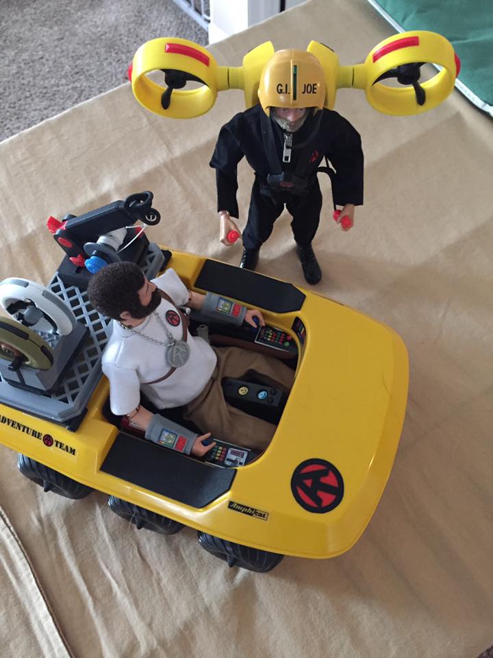
The GI Joe Adventure Team Vehicle (ATV) is a highly prized possession among Joe collectors. Many collectors have multiples. Originally, the ATV was sold in one of the most iconic GI Joe Adventure Team sets of all time – “Secret of the Mummy’s Tomb”.
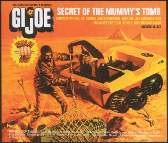
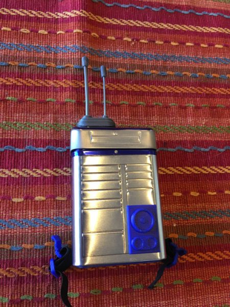
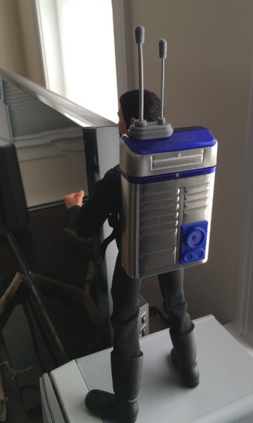
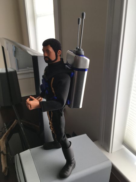
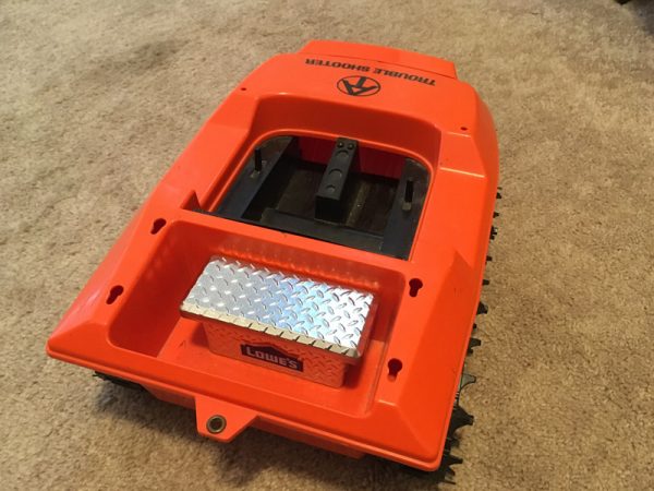
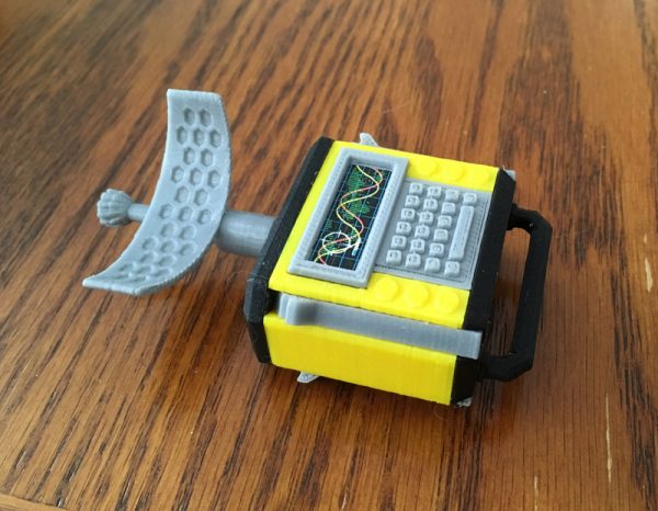
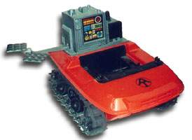
This versatile six-wheeled vehicle came with a winch to haul up a newly-uncovered mummy. But it was far cleverer than that. Remove the winch, and you could put cargo rails into four slots in the body of the ATV. Those slots would later be re-used in a new version of the vehicle, now with tank tracks, called “The Trouble Shooter”. Now, a large electronic radio (with talking technology) would take up those four slots.
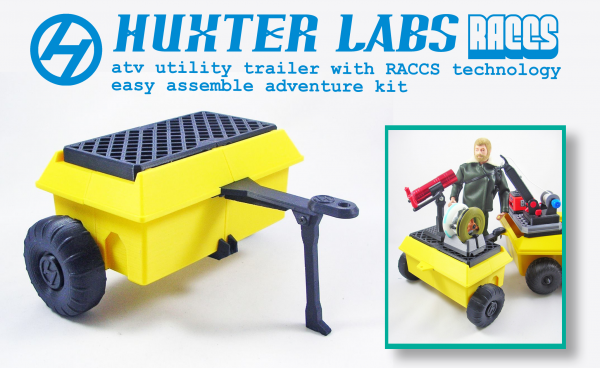
“Could make it RACCS Compatible too…“
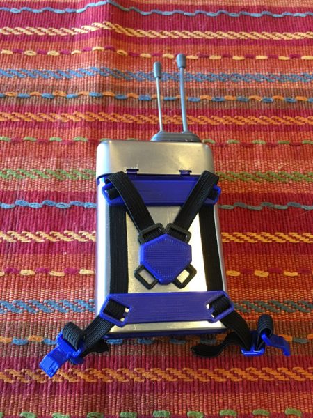
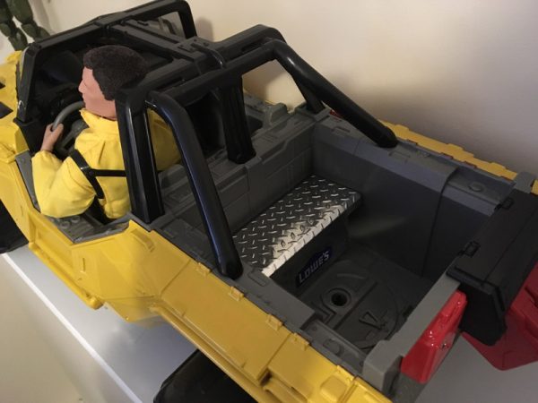
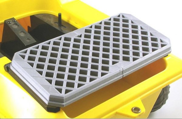
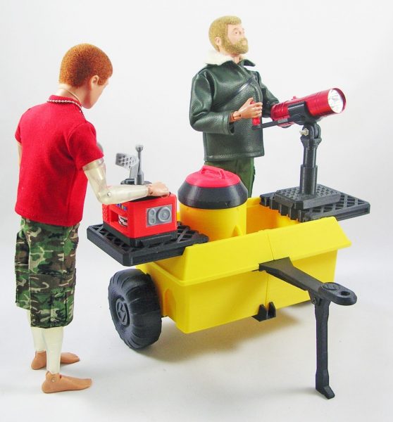
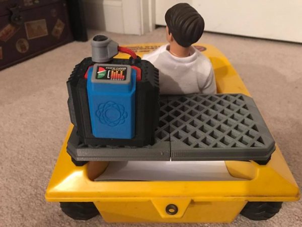
One of the most versatile toys I have created was a collaboration between Greg and me. He wanted a platform that could fit over the cargo bay of the ATV/Trouble Shooter, which would fit into those four slots and hold various adventure equipment.
I wasn’t sure how that would work since my printers can’t print an object big enough to span that space. However, soon enough, I came up with a grid system on a two-part platform that snapped together for easy storage. Pegs on each side would snap perfectly and snugly into those four slots.
Greg wanted the new trailer to be able to slot the RACCS platform into it.
I did him one better.
The Plans
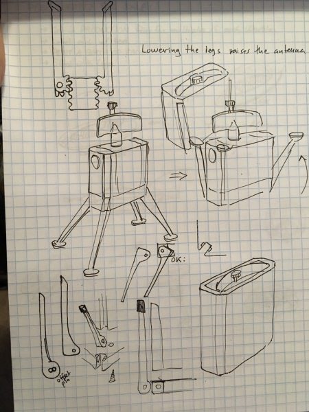
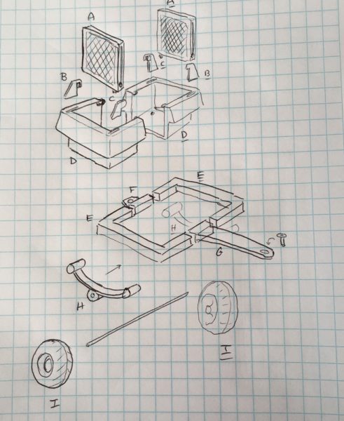
I began sketching, and while these are very rudimentary sketches, I shot them and sent them to Greg who seems to have no problem understanding what I’m trying to get across, though my drawing skills are not on display here. They are very rough sketches to flesh out the ideas:
This one shows my original concept as two halves, with the RACCS attached by separate tabs. The cargo section would fit into a frame, with curved springs for the wheels, and a metal axle between the wheels, riding under the body.
I changed a lot of that, to make it much simpler. I didn’t have to cut a metal axle, the plastic is strong enough to handle being a thick axle. And to avoid screwing or gluing the hub-cap into place I split the axle and made a wedge of the cap. Push the wedge into the splits until they snap and those wheels ain’t goin’ anywhere. And they spin nicely.
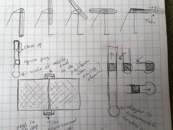
Below is a sketch of how I envisioned the built-in RACCS platform working. And it works exactly like this, and works great.
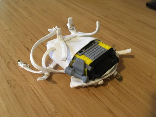
RACCS On Board
I incorporated the RACCS platform directly into the design of the trailer. And in a very clever way.
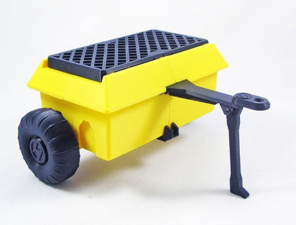
(RACCS closed and ready for action!)
Tabs in the side of the cargo body would fit into slots on the sides of slightly altered RACCS platform halves (otherwise identical to the original system) and it would allow the RACCS to slide into place over the cargo bay – and when not in use, slide out, angle downward, and store in the sides of the cargo bay itself. The tabs were square, and just fit into the slots. But at the end, those slim slots become a circle, and allow the platform to hinge upward, and then slot down the same tabs.
(RACCS out)
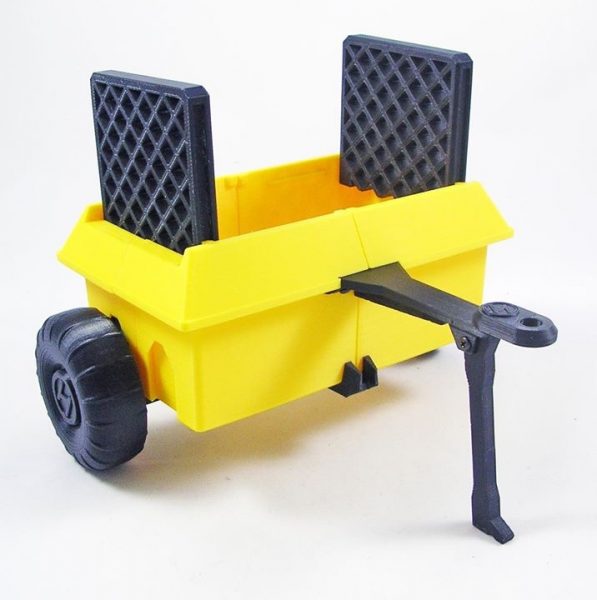
(RACCS up)
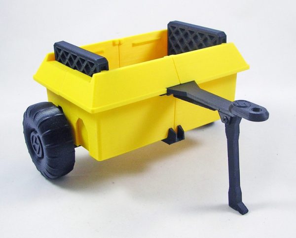
(RACCS stowed into the side.)
There are even slots in the floors for the connector pins on each side of the platform (which snap them together) to fit into.
Here’s where some serendipity comes into play:
As always I sent Greg a nearly complete prototype, and he discovered that the RACCS platform halves are fully functional when split open and pulled out to the sides. A completely unintentional bonus!
The RACCS Platform is optional. It can be removed simply by loosening the screws holding the body halves together, and re-tightening them.
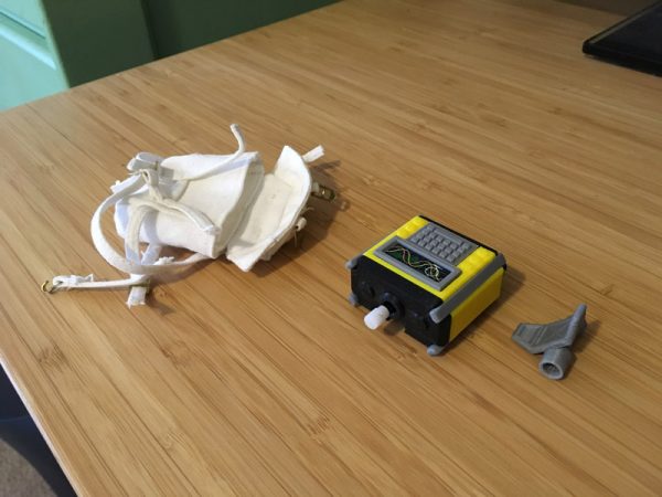
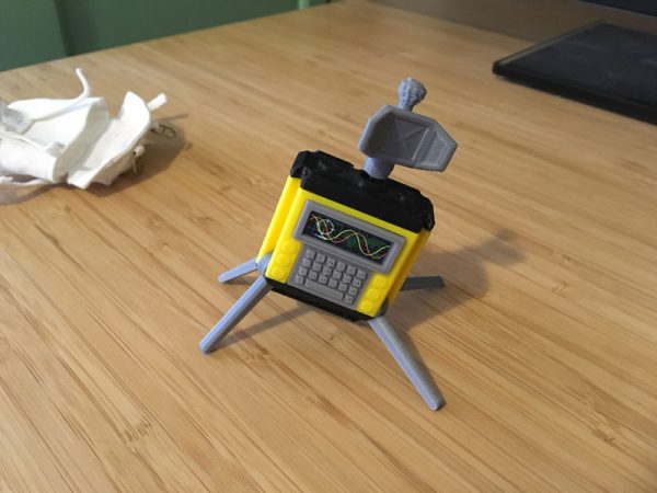
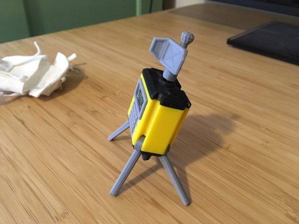
Other Features
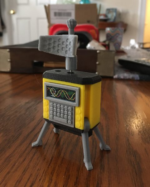
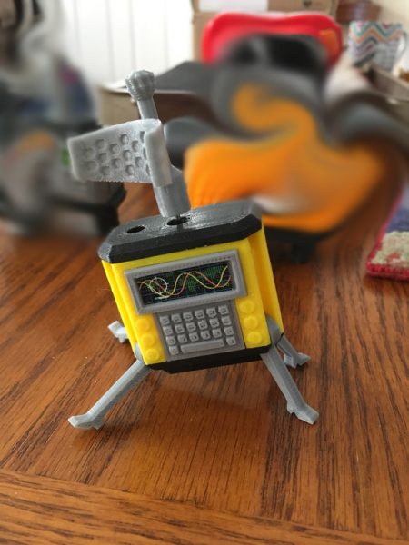
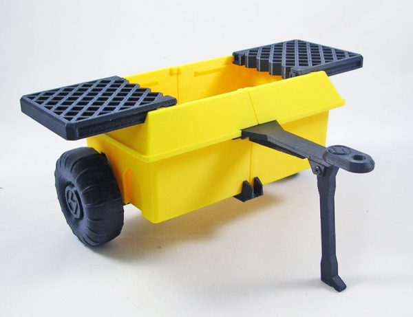
Other features I included are a folding leg which allows you to remove the trailer and have it stand upright as a mobile work station. Without this fold-down leg, the trailer would tilt forward and be useless.
Another: Notice in the original ATV there is a tab at the back with a brass eyelet. Clearly this is intended to tow cargo, but to my knowledge, HASBRO never used this feature.
This allows my Cargo Trailer to be towed, obviously.
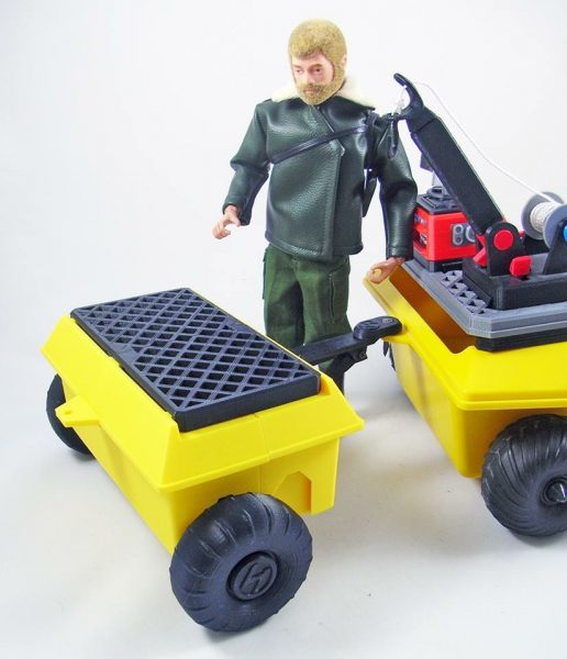
So I added an identical tab to the back of my trailer. While the photo above shows it without the brass eyelet, I managed to find some perfect brass eyelets that fit like a glove into the tab, and acts identically to the original.
The upshot is you can daisy-chain these trailers as many as you like.
I took a photo of prototypes in a train:
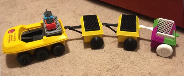
The funky psychedelic one at the rear is an early print. I almost always print in colors I have a lot of but don’t use a lot. No need to waste the final colors on a prototype meant to test fit and function.
Sold As A Kit
Due to the size of this toy, I knew shipping a number of them to Cotswold Warehouse would be trouble, so Greg and I opted to offer this up as a kit. So I had to make it easy to assemble.
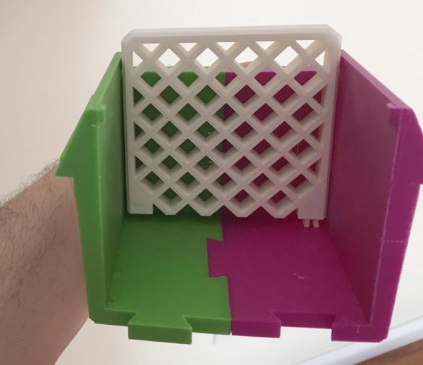
My printer’s maximum print capacity is not large enough to print the body as a single piece. So I had to cut it into four corners and make puzzle pieces out of them so they could snap together nicely.
If I was assembling it myself, I might just glue the parts together. Since Super Glue bonds to ABS so strongly it’s almost impossible to break, that would have worked fine.
But if people were going to assemble it, I wanted it to be as easy as possible.
So it’s designed to go together with screws, and as efficiently as I could engineer.
I also designed the body to be symmetrical. The wheels can fit into any slot on the sides, and the tow arm and rear hitch can fit into either end. This meant symmetrical screw holes too.

Two screws hold the sides together, and two each hold the tow arm and rear hitch, which has the dual purpose of attaching those pieces, and joining the two halves of the body.
A single screw connects the leg latch to the body. There are two screws to keep the axle assemblies on.
I used a metal nail, with the tip cut down, as a hitch peg, for strength.
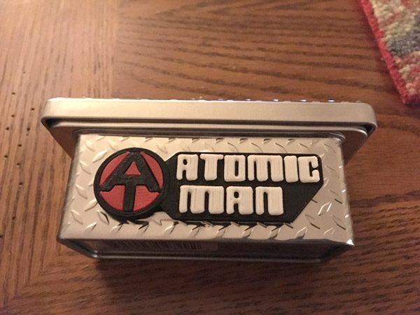
I was able to use the Huxter Labs logo for the first time! I put them on the hub-caps and the tow arm.
![]()
Based on the AT Logo, I turned the A and T into an H which has a sort of L on the upper left.
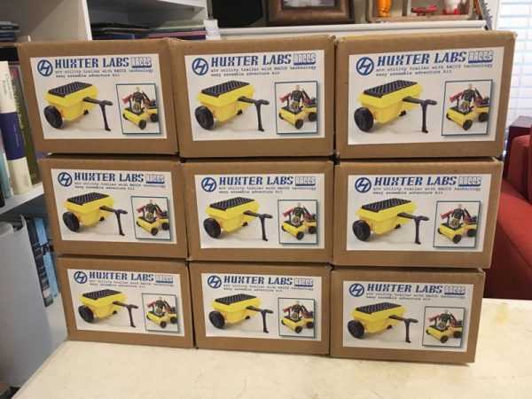
Packaging
Normally when I ship my toys to Cotswold Collectibles, I use zip-lock bags and bubble-wrap, and pack them into large boxes. For this toy, sold as a kit, I would have to do something new.
I bought a bulk order of 4x6x6″ boxes to sell products on my ETSY store. These, it turns out, were perfect for packing this kit into. I worked out a fit system that allowed me to put a body corner in, put an axle on that, cover it with another body corner, repeat, then put the RACCS platform halves between them, the wheels on the side, and the rest of the parts in a zip-lock bag (including the screws and tow bolt) and they fit perfectly.
I printed instructions to fold into the package, and I printed a label for the box.
I used yellow duct-tape (AT Yellow) as my signature box seal.

My first fully packaged toy!