Menorah for a Friend

For Hanukkah this past year I made this for a friend.

menorah-01

I’m sure it’s not perfect, but I did try. Each holder has a bolt to prevent melting of the plastic. This s really a prototype. I had hoped to print it in metal at some point but that would be incredibly expensive. The Shamash (helper holder) is the tallest one at the back and contains a blue candle. These are simply birthday candles, and this Menorah was meant to be symbolic, not actually used (since buring the candles down will likely melt the adjoining holders.) But I enjoyed making it for her.

Luxury Rocket

In my continuing series of rocket designs, I spent some time last week designing a sleek rocket whose fins sweep down the entire length of the body.

lr-full-01

It’s hard to see, but rivets line the body on either side of each fin, and along both rims of the engine section. The window is printed in glow-in-the-dark blue because I like how that looks as reflective glass.

Here is the underside, showing re-use of an engine detail that I modeled for an entirely different purpose but have used in several projects since.

lr-rear-01

It was first designed for a GI Joe project, an ice blaster.

at-ice-blaster-front-view-01I used that central core (fused into one part) to create a jetpack for a Corgi which I designed and printed for a friend. (I did not design or model the dog, I just used it with my own jetpack design.)

I also used it on my Jetpack Rocket:

rocket-jetpack-2

My rocket collection so far:

2015_04_rocket_collection

Left top right: Luxury Rocket, Rocket Jockey Ship, Silver Bullet Rocket, Fathers Day Rocket, 3DAGOGO Rocket, Jetpack Rocket, Regular Joes Rocket(s). (One for me and one for each of the Regular Joes.) (That’s the Regular Joes Podcast, which, if you’re not listening to it, you’re missing out.)

Jetpack Corgi!

My friends Chonny and Jess have two corgis and Chonny and I once discussed 3D printing a corgi with a jetpack. While I would find modeling a corgi arduous, I was not above downloading one. I can’t remember where I found it but I did manage to find a good corgi. The body was a bit long, so I cut that down a bit. But I did design this jetpack with the Rocketeer jetpack in mind.

jetpack-corgi-02

jetpack-corgi-03 jetpack-corgi-04 jetpack-corgi-06

Rocket Jockey Rocket – My Unapologetic, Blatant Rip-Off

I admit it. I really liked coolrockets.com‘s Space Tub. I have one here. I’m thinking of selling it, though, as I really have to get rid of the bulk of my toy collection. Here it is:

coolrockets-space-tub

So before bidding this one a fond farewell, I opted to make my own version of it, with minor changes, so I don’t have to be lonely no more.

Here are the parts:

rocket-jockey-parts-01

Body in two pieces, rear and front, pegs to fit them together, a cockpit which has two window sections, unlike the original, a cowl to fit around the cockpit, with a fin slotted into the cockpit, and two on the sides, which form a perfect triple rocket. Top it off with an engine and nose spear.

And it looks like this when completed:

rocket-jockey-assembled-sitting-01rocket-jockey-assembled-01

And to finish it off, to be like the original, I added a sewing pin:

rocket-jockey-pitot-tube-01

And here he is alongside his larger brother (printed at 1.44x scale) with a slightly larger sewing pin:

rocket-jockey-with-big-brother-01


Silver Bullet Rocket

I love retro-designed rockets. I’ve done several now, and I’m just getting started.

This one is designed after some 1930s ideas, and is even similar (though mine has fins) to the one that took Bugs Bunny into space to meet Marvin the Martian for the first time.

Here’s mine, the parts laid out:

rocket-silver-bullet-parts

Which assemble to form:

rocket-silver-bullet-pose-02  rocket-silver-bullet-pose-01

So far I have designed and printed a rocket based on a Fathers’ Day Card my daughter gave me:

rocket-fathers-day-first-test-print

Then I did one from the 3DAGOGO T-shirt from a contest I won:

3dagogo-rocket-with-shirt

Then I did one for the Regular Joes Podcast after their new logo, a white and gray rocket:

rocket-regular-joes-01

Then last weekend I designed the Jetpack Rocket (based on the jetpack I made for my friend, which I modeled on a corgi dog for him.)

rocket-jetpack-1

UPDATE: May 2, 2015 – PLA Version

A while back I got a reel of Afinia Premium PLA filament in gray. I had never used PLA before, and for some reason I had some issues printing on my H479. I don’t know why. I more or less abandoned it as a material after a few tests. Then I got a Makerbot red transparent PLA not realizing it was PLA. I thought it was ABS. I used that a couple of times with similar results. A lot of spiderwebbing (very thin traces of filament stretching between spans between parts.)

This week I revisited the PLA with my H480 (basically the same printer with some nice extra features, but more or less the exact same printing system) and this time I got really good results. So I thought I would do a more comprehensive test print of my Silver Bullet Rocket.

So I printed each piece in Fine (slowest, most accurate) mode, with .15mm layers (highest resolution) in PLA.

Here are the results:

The Parts: (minus the door window, because I forgot I needed it when I took this picture.)silver-bullet-pla-test-parts

The door, with aforementioned window (printed in blue glow-in-the-dark ABS. This is the only ABS part on this particular print) – But look at it close-up. It printed very nicely!silver-bullet-pla-test-closeup-door

The engines and caps: (I have to say, I really like that translucent red!)silver-bullet-pla-test-engine-closeup

The nose section. (At this size, the cone was a little untidy)silver-bullet-pla-test-nose-closeup

The finished print.silver-bullet-pla-test-full

Claus-Bot – New Bot Shoppe Robot

claus-bot-01

It was Carol’s idea! I swear! She envisioned a Santa Claus robot, and of course its main feature would be disproportionately large claws.

So I set to work designing a slightly retro look, with white helmet reminiscent of the Battlestar Galactica Viper pilot helmets (original series) with a fin that looks like it belongs on a bullet train from the 1920s.

I was originally going to give him skis and a jetpack engine, but I thought better of it. I thought of snow-cats, which have very wide treads, and completed the design with white jet intakes down the front  and a headlight beam on his belt buckle, and snow goggles.

claus-bot-02 claus-bot-03

ZoomFloppy Case

ZoomFloppy is a great little circuitboard I bought for $35.00. It connects to a PC through USB and allows you to connect Commodore 64 disk drives (1541, 1541-II, 1571, 1581) directly to the PC for reading and writing to .d64, .d81 files, etc. This allows you to use a Commodore emulator (like VICE) which uses these files as images of the original disk.

zf-zoomfloppy

It’s a great way to archive your old disks too, but also to revive your interest in the Commodore 64 without having to go out and find an old C64. Any PC (or Mac, or heck, even a Raspberry Pi) can run the VICE emulator and you can have a fully functional Commodore 64 at your fingertips.

c64_startup_animiert

To start, I measured the distance between the mounting holes on the circuitboard:
zf-caliper-measure-topzf-caliper-measure-sides

(Note, the numbers on the calipers are not accurate… this was for visual reference only.)

Then I printed an X-shaped test strip with cones where the screws should go, so I could test fit it onto the circuitboard and see if I had the dimensions just right:

zf-screw-test-confirmation zf-screw-test-fitting

Once I knew the test cross fit, I could be confident those dimensions would work on the case.

I measured the connectors so I could cut spaces for them, and printed a rough frame that should fit the ZoomFloppy:

zf-case-test-1-bottom-frame zf-case-test-1-bottom-test-fit

Then I did it again, refining the spaces in the gaps for each connector, and rounding out the hole for the LED, since the square hole was just for position testing.

zf-case-test-2-bottom-frame zf-case-test-2-test-fit

When that was secured, I printed a completed bottom:

zf-case-test-bottom-full

Then I printed a test top, though this print came out less than perfectly, I was able to use it to test position:

zf-case-test-top zf-test-case-top-fitting

It was time to print the first test print in color – white.

zf-case-halves

I printed these floor down. My printer was having some issues with warping and the case top and bottom did not come out perfectly flat, but I think that’s a print-bed heating issue I’m working to resolve. But it worked out fairly nicely. Printing it “upside down” allows the connection between the top and bottom halves to fit just about perfectly. The warping would only affect the case top and bottom, and not be a major issue.

I etched out a space for a Commodore logo, and a strip at the top that would have a smaller version of the logo with the rainbow color strips familiar on the Commodore 64’s case, then the ZoomFloppy logo on the right. Each strip was printed in a separate color, and fits into a thin slot on the logo strip.

zf-case-detail

Next I secured the two halves with screws, sandwiching the ZoomFloppy board perfectly.

zf-done

This shows the bottom, with the four screws and the four rubber feet I attached to prevent slipping. (Bought in any craft or hadware store.)

zf-case-bottom

Thunderbird 4 – A 3D Print

tb41

I have been looking for good models of the Thunderbird rescue craft that I did not want to bother to model. Thunderbird 1 and 3 were ones I wanted to model, and thought I could do a good job. However, the curves and nuances of TB2 and TB4 made me not want to go through the trouble. TB5 I could do easily, but I’m not sure I want to.

So recently I found a model of Thunderbird 4 on Thingiverse. But it had some issues.

First, it was solid. I wanted it to be printed in colors. Also, various bits were just thin polygons placed in the mesh, not combined and not closed.

I remodeled those bits, then split the body in half, adding detail, and 3 screw holes to fasten the two body halves together.

All parts

Yellow: Front, rear, engine hoods, fin, nose, lightbar arm.
Red: Stripes and engine housings
Silver: Grill engine inserts
Blue: Windshield and dome
Clear: Lights – raw filament
tb4-parts-all

Adding red engine housing stripes and grills:tb4-grills

Attaching front and rear with 3 screws:tb4-body

The screws:
tb4-screws

Nose stripe:
tb4-nose-stripe

Nose:
tb4-nose

Engines:
tb4-engine-housings

Attaching engines:
tb4-rear

Adding fin:
tb4-fin

Adding light bar:
tb4-lightbar

Windshield and dome:
tb4-windows

Clipped filament strands to fit the light fixtures: (Fuzzy picture, sorry.)
tb4-lights

Result is rather nice, even though I had to work hard to get the flat bases (where the body halves meet) to print flat. My printer has been warping up things with large flat surface areas. But it’s not a bad model.

tb4-finished

The More Printers The Merrier

This is a short video (no sound, sorry… my iPhone’s front microphone does NOT work when shooting video) showing my new H480 printer (left) working at the same time as my H479 (right).

It is currently printing two halves of a case designed to house a circuit board called ZoomFloppy which allows PCs to read and write to Commodore 64 disk drives.


Arduino Six Sided Die

As a simple project, I decided this morning to tackle the six sided die project. That is a simple random number generator that displays its result on a six-sided die.

dice-breadboard-01

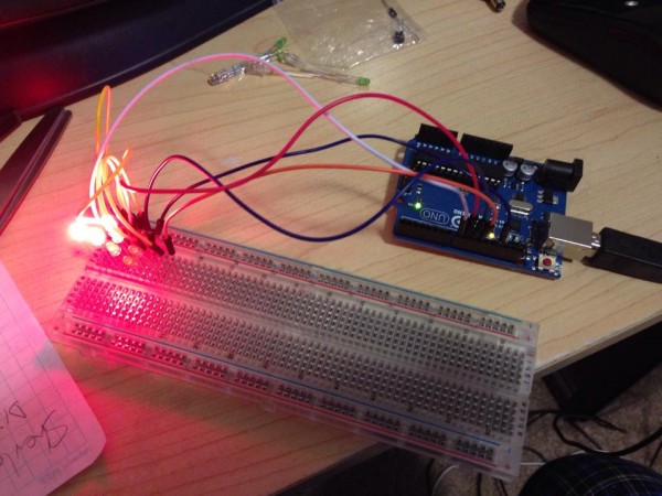
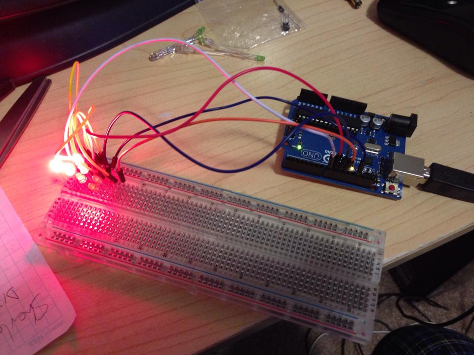
This picture shows the LEDs lit up to represent 5, but the lights are so bright in the pic it’s hard to distinguish.

A six sided die has seven possible pip positions, and an LED can represent each. Lit, it represents a pip, unlit it represents a space.

One might think the simple solution would be to control 7 LEDs individually, so that when you roll a 1, you turn on the center pip. Roll a two, turn on one in a corner and one in the opposite corner, individually, and so on.

dice-7

However, when you think about how dice are marked, you really only need four output controls:

dice-a dice-bdice-c  dice-d

Because:

1 = dice-a

2 = dice-b

3 = dice-a and dice-b

4 = dice-b and dice-c

5 = dice-a and dice-b and dice-c

6 = dice-b and dice-c and dice-d

So any combination from 1 to 6 can be represented with just four states.

That means you only need four output pins on the Arduino. One is hooked up to just one LED, but the other three turn on TWO LEDs at the same time.

The rest is all in how you place the LEDs in space. I will 3D print a plate that puts the LEDs in the right places, and then solder the wires to control them appropriately.

The sketch, as Arduino code is called, follows:

It’s fairly straightforward. I assign numbers to variables for PinA, PinB, PinC, PinD (in case I should want to change those output pins quickly without having to change a bunch of code). Then I need a random seed, which generates pseudo random numbers each time random(x) is called. That seed creates a fixed sequence of seemingly random numbers. But with a constant seed, it will always pick the same random numbers in sequence. So I use an analogRead on a pin that has nothing attached to create the seed. This creates a more random sequence because the seed is different each time.

Then I tell the four pins I’m using to be OUTPUT pins. Serial.* allows me to write standard text output to a monitor so I can see what’s going on in there.

Then I simply pick a random number between 1 and 6 and then use that number to tell which pins to turn on (HIGH) and which to turn off (LOW).

int PinA = 8;
int PinB = 9;
int PinC = 10;
int PinD = 11;
float seed;
int Number;
int Display; // the variable needed to run my display function

void setup() {
// put your setup code here, to run once:

pinMode (PinA, OUTPUT);
pinMode (PinB, OUTPUT);
pinMode (PinC, OUTPUT);
pinMode (PinD, OUTPUT);

seed = analogRead(0); // get a fairly random value from an unconnected analog pin

randomSeed (seed); // initiate a random seed

Serial.begin(9600); // Prepare to write to the monitor

Serial.print(“\nRandom seed – “);
Serial.print(seed); // write the seed to the monitor so I can see if it’s fairly random

}

void loop() {
// put your main code here, to run repeatedly:

Number = random (6);
Number = Number + 1;
Serial.print(“\nRandom number – “);
Serial.print(Number);

// HERE INSERT CODE TO LOOP 20 TIMES, with A*time delay (so each delay is longer) calling random, then DICE(Number)
// This gives the impression the die is rolling random values until it stops picking the last one.

Dice(Number);

if (analogRead(0) < 100000){
delay (1000000);
}

}

void Dice(int myNumber) { // function to display the Number using LEDs
Serial.print(“\nNumber passed to function – “);
Serial.print(myNumber);

// reset pins – turn off all LEDs first
digitalWrite(PinA, LOW);
digitalWrite(PinB, LOW);
digitalWrite(PinC, LOW);
digitalWrite(PinD, LOW);

// Now turn them on based on myNumber
switch (myNumber){
case 1: {
Serial.print(“\nSwitching on 1”);
digitalWrite(PinA, HIGH);
digitalWrite(PinB, LOW);
digitalWrite(PinC, LOW);
digitalWrite(PinD, LOW);
return;
}
case 2: {
Serial.print(“\nSwitching on 2”);
digitalWrite(PinA, LOW);
digitalWrite(PinB, HIGH);
digitalWrite(PinC, LOW);
digitalWrite(PinD, LOW);
return;
}
case 3: {
Serial.print(“\nSwitching on 3”);
digitalWrite(PinA, HIGH);
digitalWrite(PinB, HIGH);
digitalWrite(PinC, LOW);
digitalWrite(PinD, LOW);
return;
}
case 4: {
Serial.print(“\nSwitching on 4”);
digitalWrite(PinA, LOW);
digitalWrite(PinB, HIGH);
digitalWrite(PinC, HIGH);
digitalWrite(PinD, LOW);
return;
}
case 5: {
Serial.print(“\nSwitching on 5”);
digitalWrite(PinA, HIGH);
digitalWrite(PinB, HIGH);
digitalWrite(PinC, HIGH);
digitalWrite(PinD, LOW);
return;
}
case 6: {
Serial.print(“\nSwitching on 6”);
digitalWrite(PinA, LOW);
digitalWrite(PinB, HIGH);
digitalWrite(PinC, HIGH);
digitalWrite(PinD, HIGH);
return;
}

}
}

UPDATE: 2/27/2015

Obviously it wasn’t enough to just have the Arduino choose a random number and then go into an infinite loop so that resetting the Arduino would be the only way to choose another random number (or roll the die). Resetting the Arduino can take a few seconds.

So I coded in a loop that checks for a switch. The goal was that while the switch was on, random numbers would just keep rolling until you let go the switch, then the die would roll 20 more times, slowing down each time until it finally landed on the final random number. That would be the completed roll of the die.

I spent a lot of time playing with various input devices including a SPST push-button switch pressed into the breadboard, connected to an analog input. Weirdly, as I went to push the button, the die began rolling even before my finger got to the button. I pulled it away and the die rolled down to the final number. Approach again, and it would roll.

It seemed I had invented a proximity switch from a simple push-botton on/off switch.

Turns out the Ardunio’s analog inputs can sense static charge in the immediate area, and as my finger approached the switch, the analog input began to jitter, and my code detected that as ON and went for it.

I then hooked that switch up to a variably-lit LED and saw that as my finger approached, the LED would begin to brighten. When I was touching the switch it was the brightest.

Weird.

Anyway, I played with potentiometers, pressure switches, slide switches but found that when I moved the simple push-botton to a second breadboard, it acted more like an actual on/off switch.

Then my die rolled while the switch was pressed, until I let go, then it rolled down, slowing, to the final number.

But I noticed that, naturally, sometimes the same roll would appear on the die when rolling down. I didn’t want that to show up twice, since it would look like the die was stuttering. So I added code to check the current roll against the previous roll, and if they were the same, to skip displaying it. So now it may CHOOSE two of the same random numbers while rolling, it will just give the illusion that it did not. And since it’s all for show except for the last number, this does not decrease the randomness of the roll.

Later I hooked up a small speaker to an PWM (Pulse Width Modulated) output, and output the randomly-rolled number multiplied by some factor, and as each number is displayed, it beeps during the display at a tone that corresponds to that number.

So it makes really cool beeping noise now while rolling, and the slowing roll-down sounds awesome, as the audio really sells the slowing of the die roll.

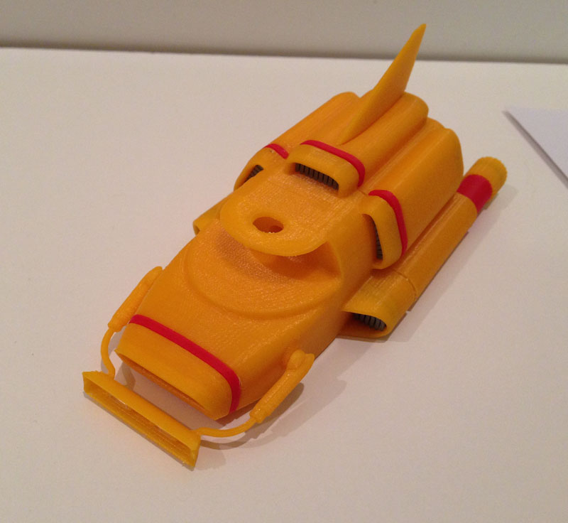
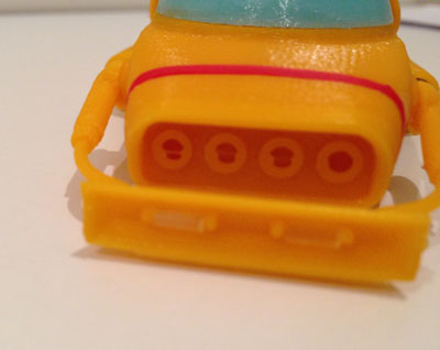
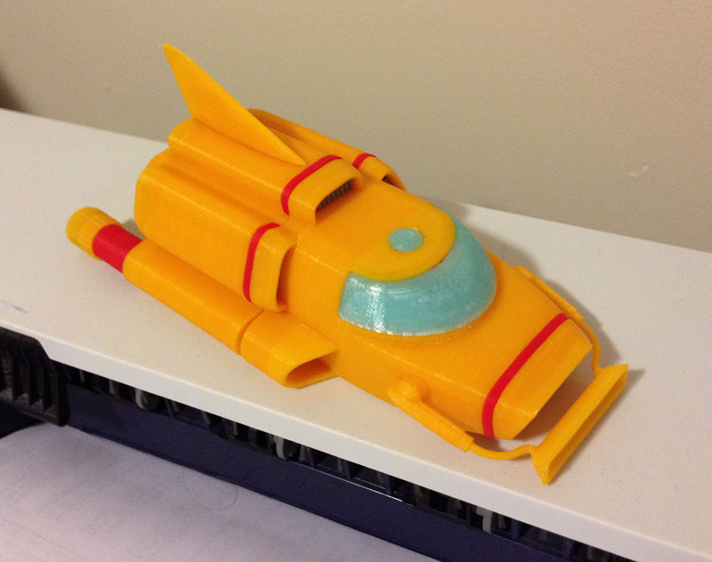
Man, now I have to move this all over to the Arduino Micro (because I want to make a housing for this die on my 3D printer).

This presents a few challenges: Powering the Micro means making a battery connect to a USB Micro jack (which is what powers the Arduino Micro) and I also need to get a light-detector working, because I’m going to be swapping out the push-button switch with a light detecting resistor on the bottom of the housing. That way, whenever you pick it up, it will roll, until you put it down, then it will roll down to the final number.

Which I think is perfect.