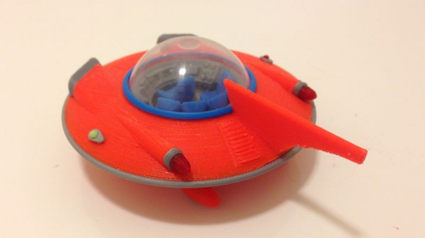
The Jetson Cruiser
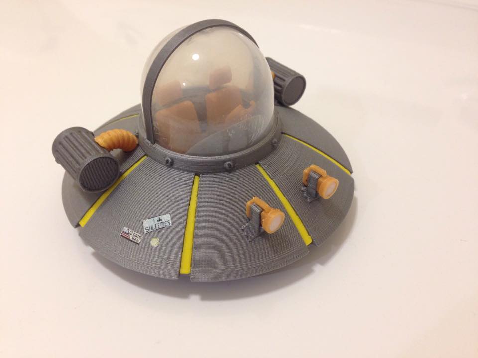
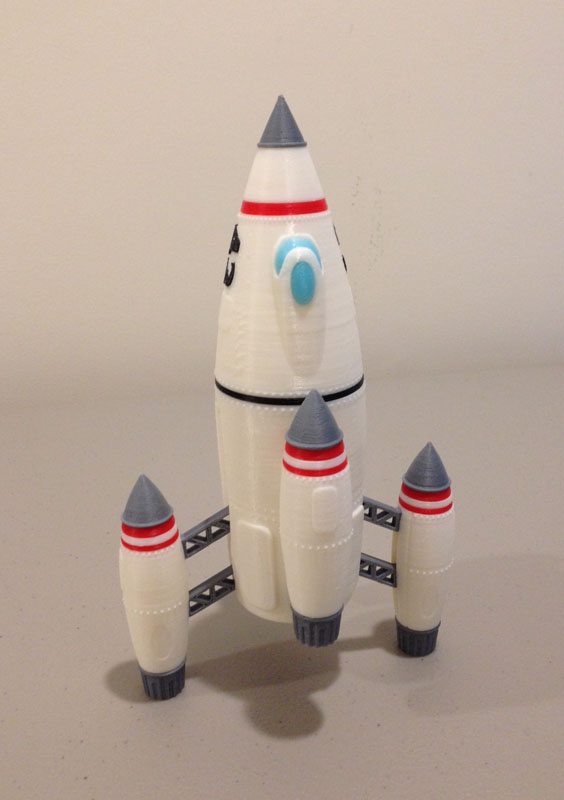
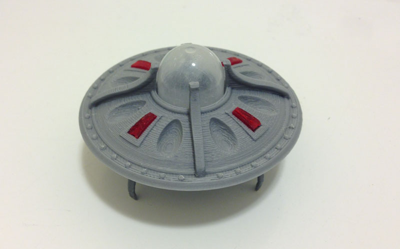
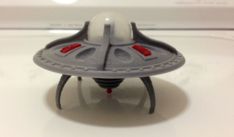
This is my latest UFO print:
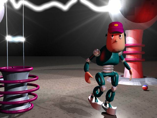
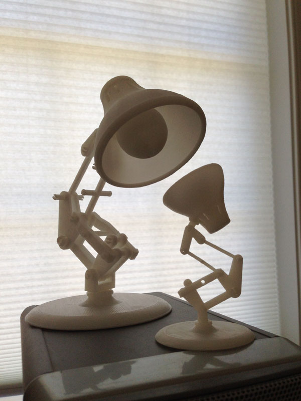
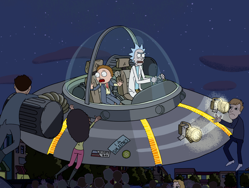
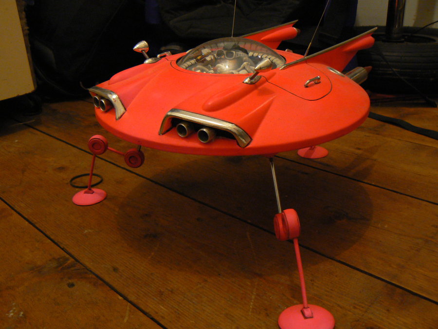
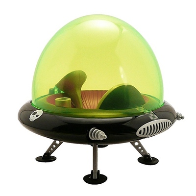
Admittedly, I grabbed the idea from this wonderful model I saw on the web:

I did make my own alterations and adjustments, though.
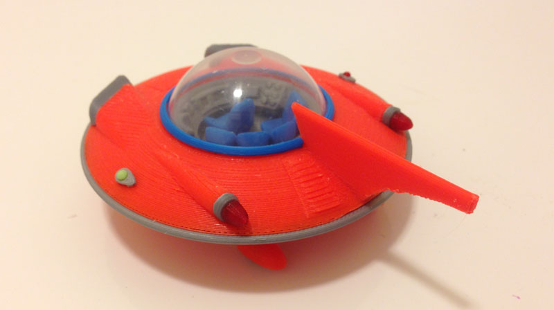
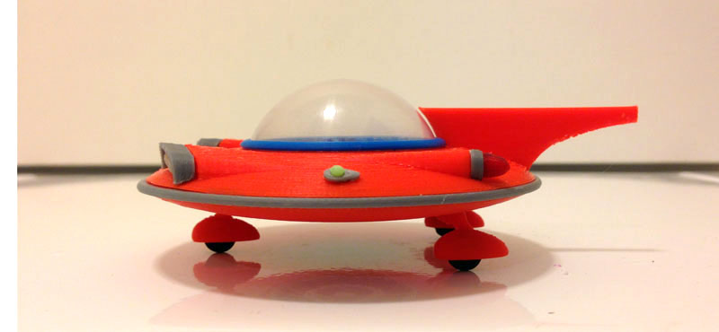
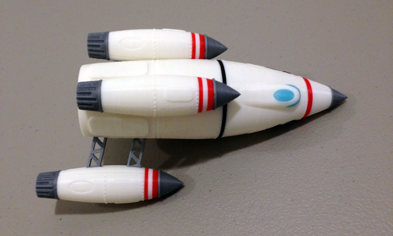
What I was aiming for was something out of the Jetsons, a flying saucer that invoked a 1950s car feel with fins and chrome lights. I have no chrome, so I was stuck with a gray filament that is called silver but is not.
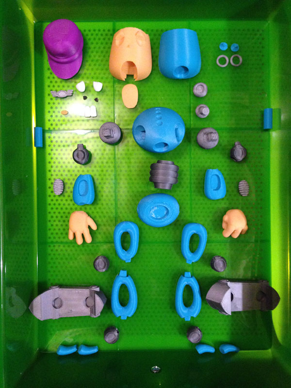
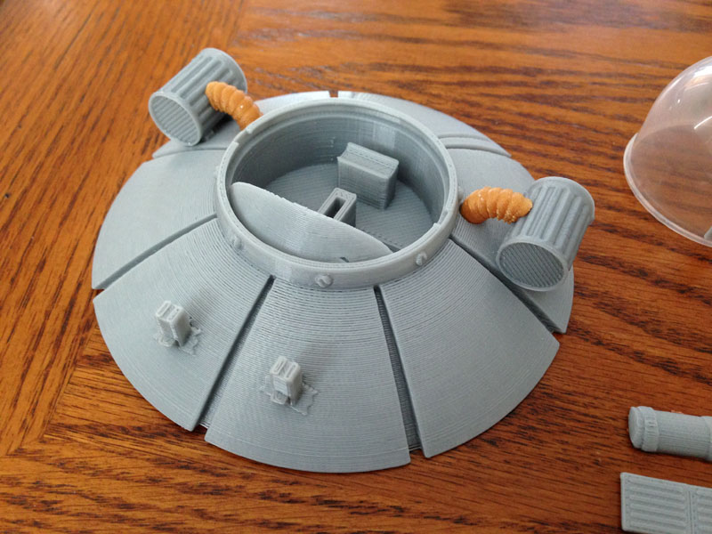
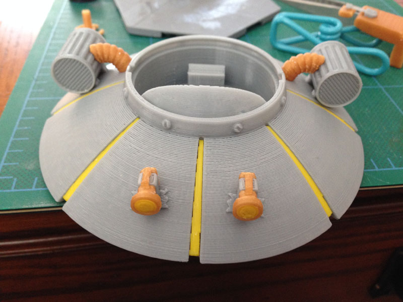
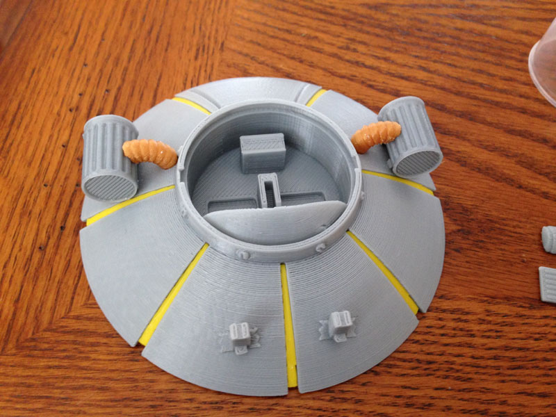
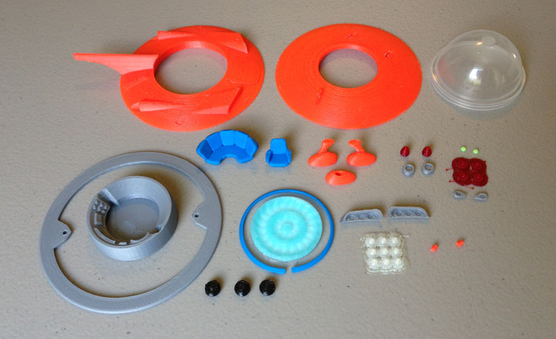
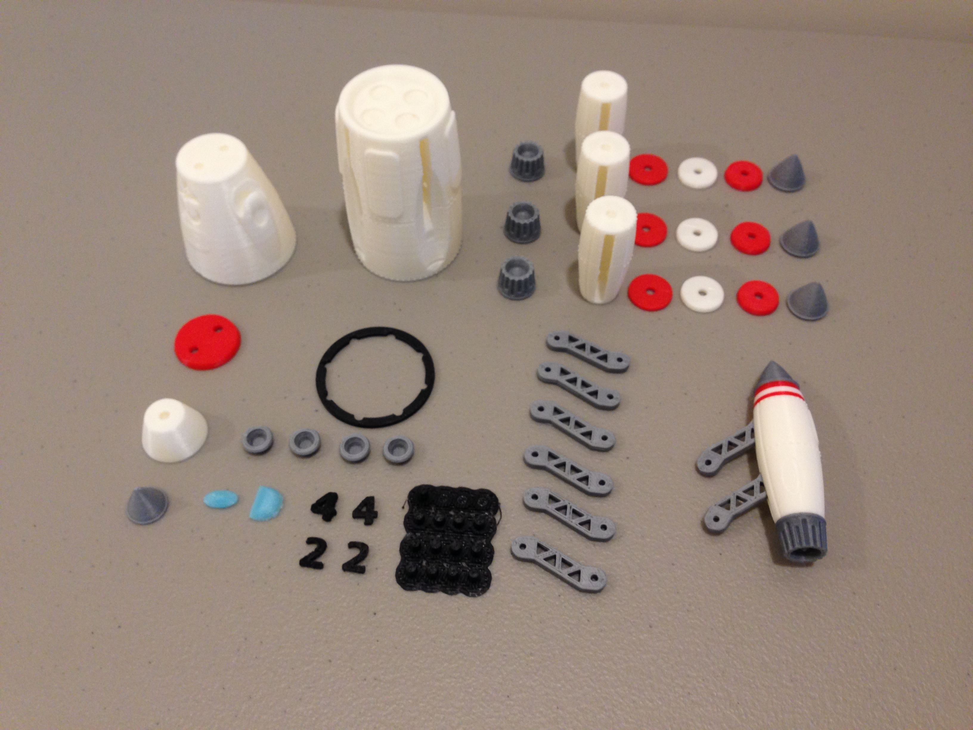
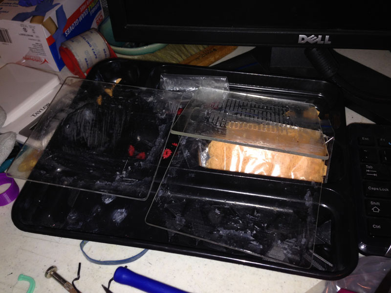
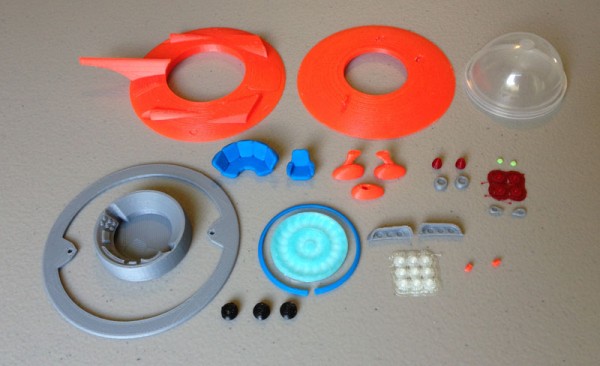
Here are all of the parts that make up the Jetson Cruiser:
Assembly
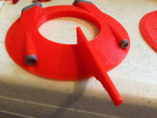
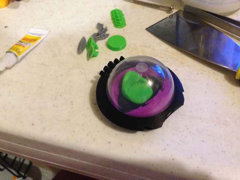
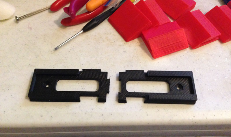
Gluing the bumper to the bottom half: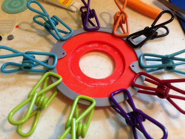
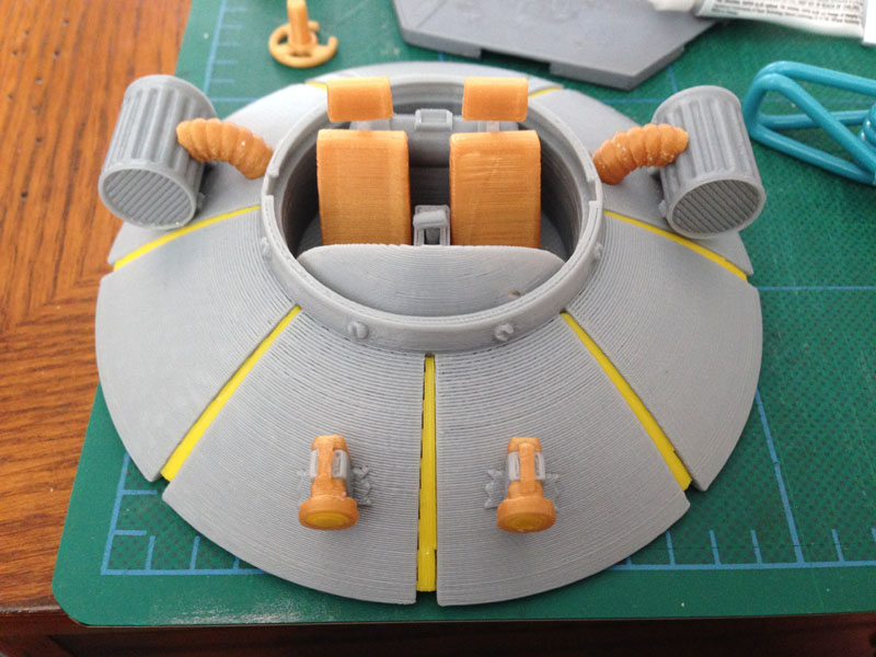
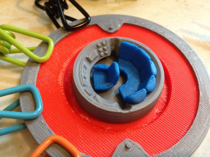
Here the cockpit assembly (console, pilot seat and comfy couch for five passengers) is attached to the bottom of the saucer:
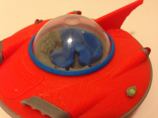
Then the semi-spherical bubble capsule cap is put in place. The fit is so perfect I don’t need to glue it: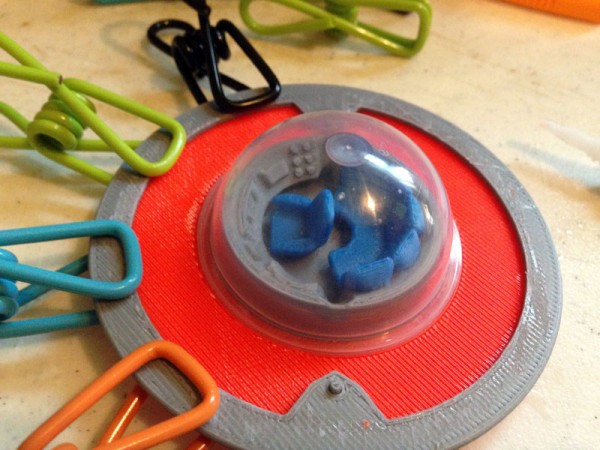
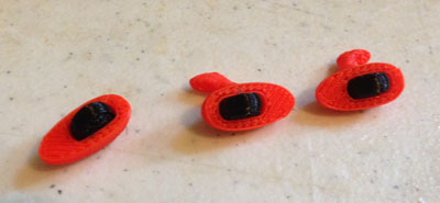
Then I blue the six clear translucent lights to the light covers: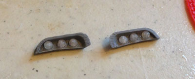
And I attach those to the body: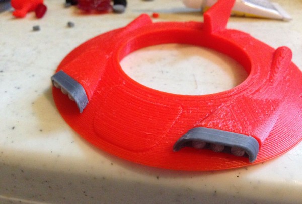
The tail-light rims go on next:
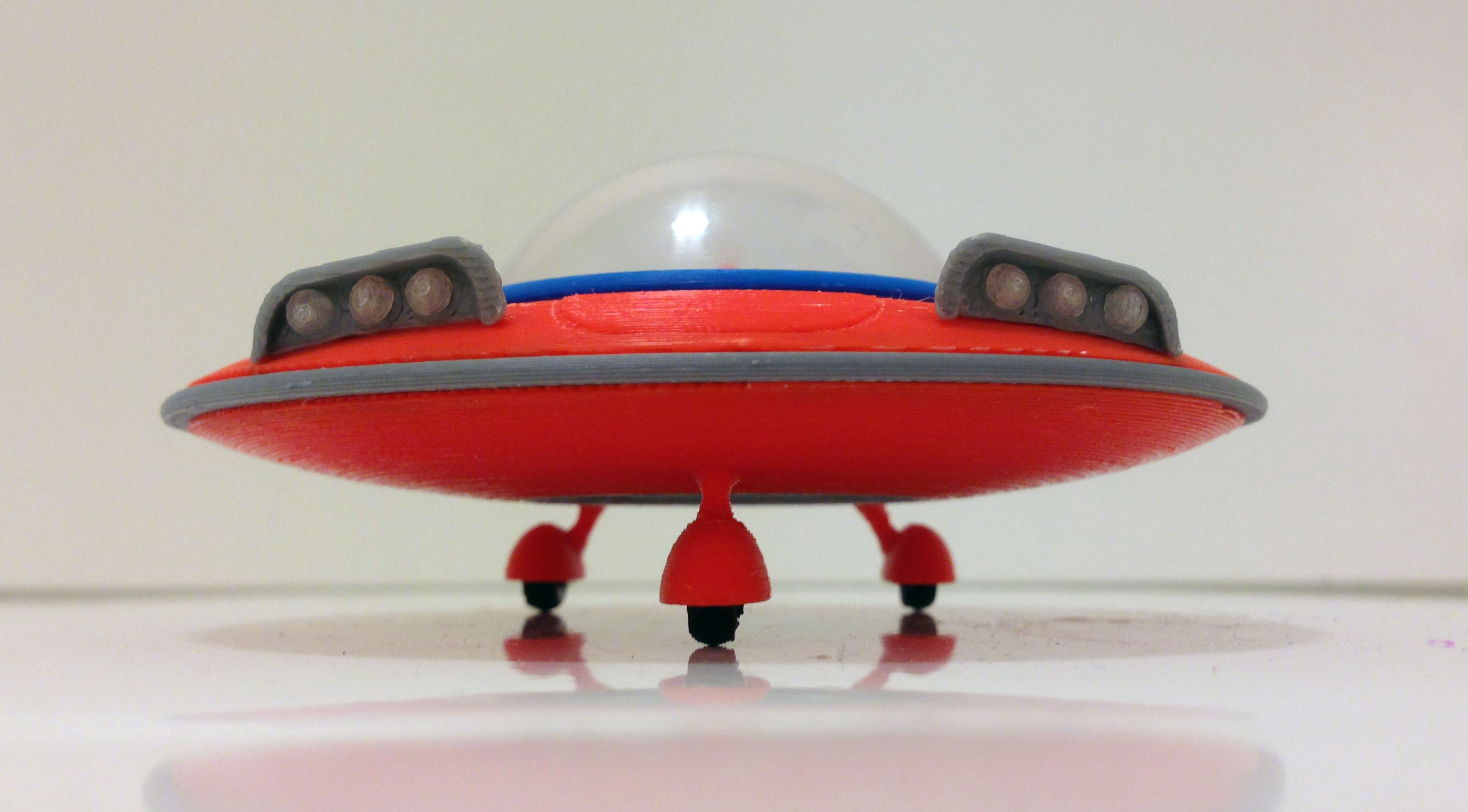
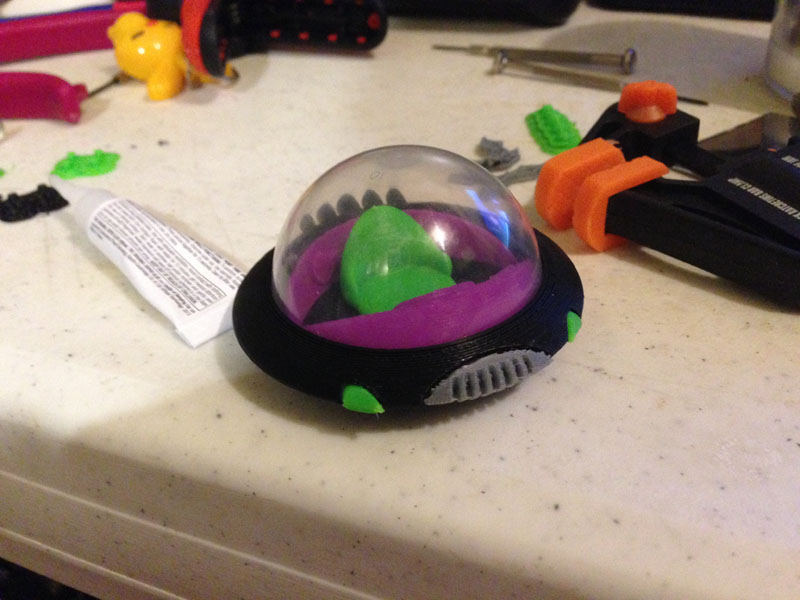
Followed by the customary navigational lights, green on the left, red on the right: 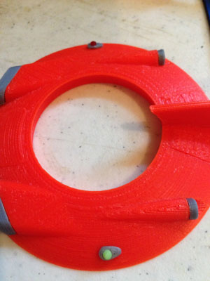
And then the actual tail lights: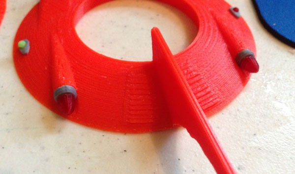
I glue tires into the three wheel housings. Note: These wheels are printed in a flexible black, so they feel like rubber and have some bounce. In a future version I may add axles and allow them to roll:
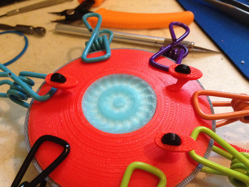
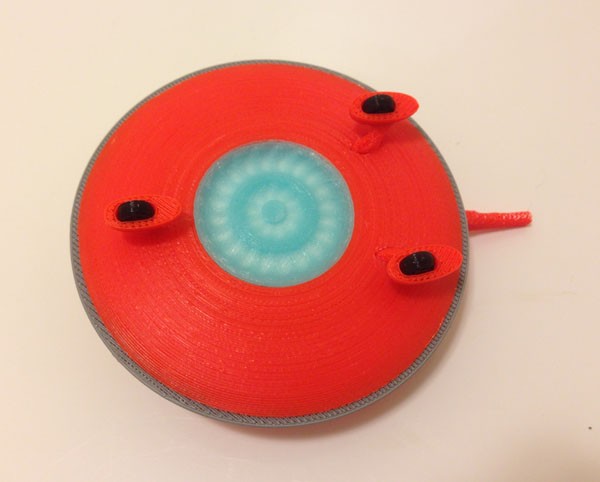
Inserting the vertical thruster. The thruster is printed in a translucent glow-in-the-dark icy blue. So when it’s glued to the underneath, it shows the orange (and gray from the cockpit) through. To avoid this, I attached a circle of tin foil to reflect light back out: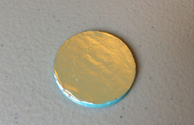
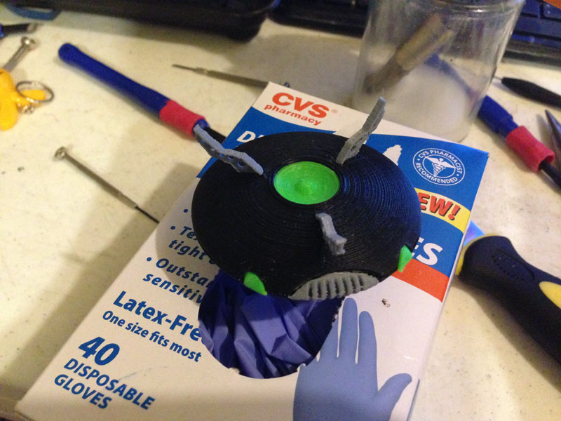
Then I glue the thruster in place underneath, and attach the wheels: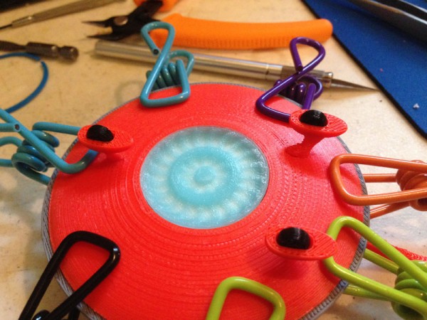
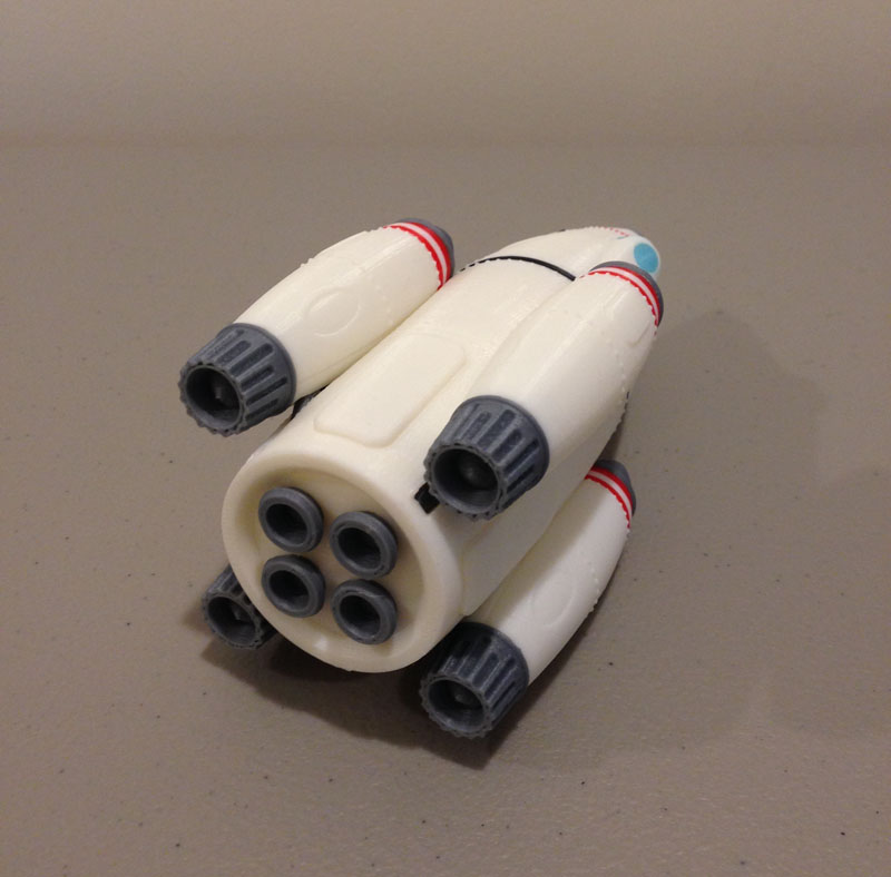
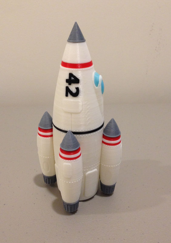
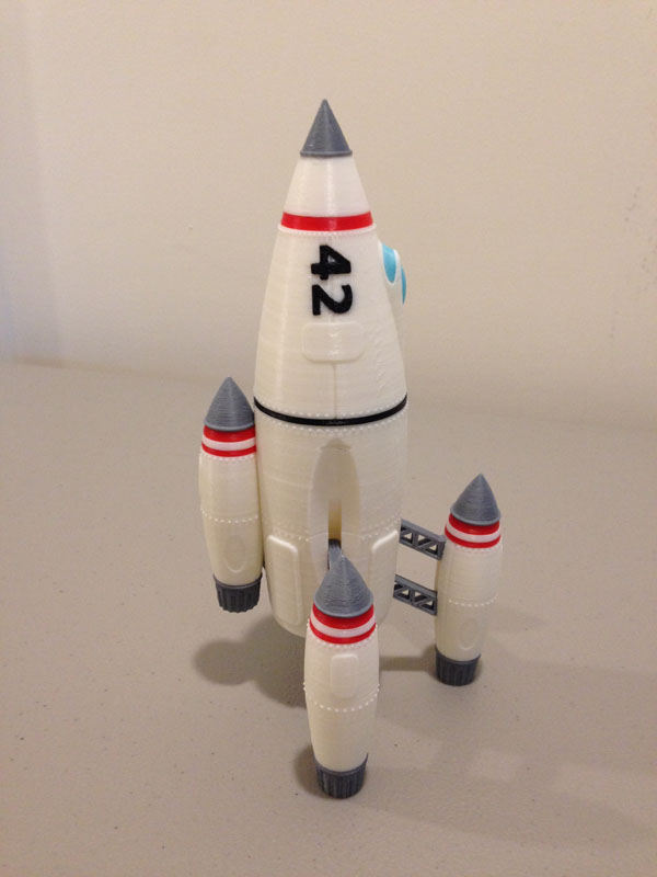
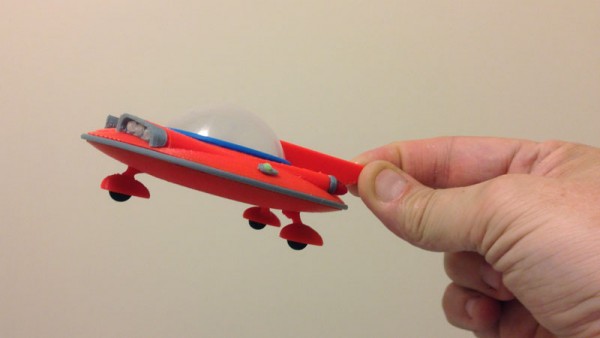
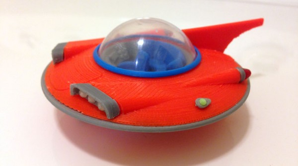
Now the two halves get joined, for a completed model: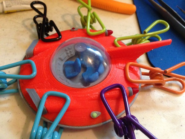
The Showroom


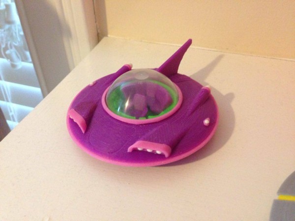
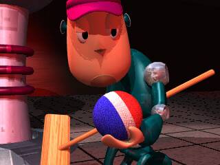
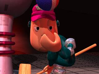
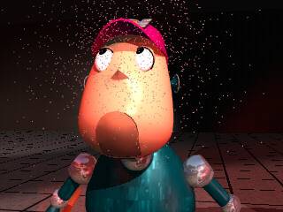
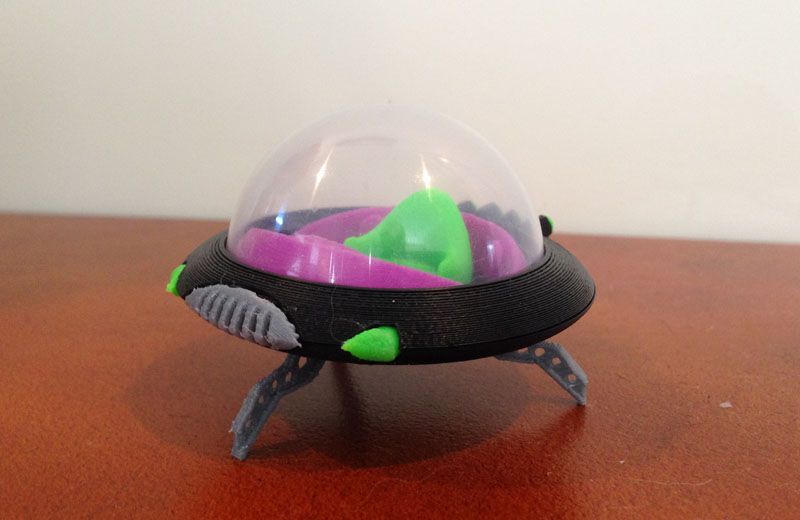
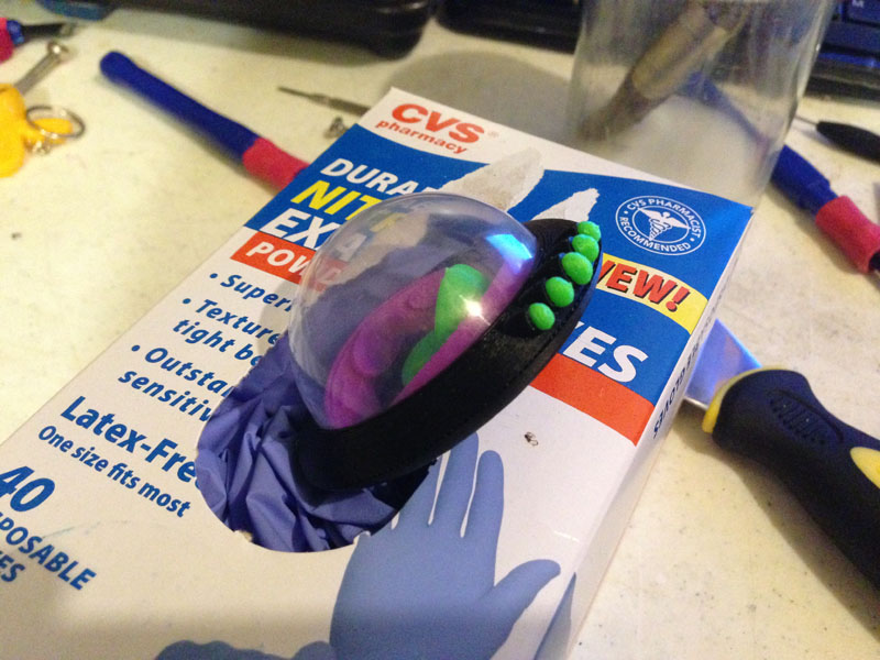
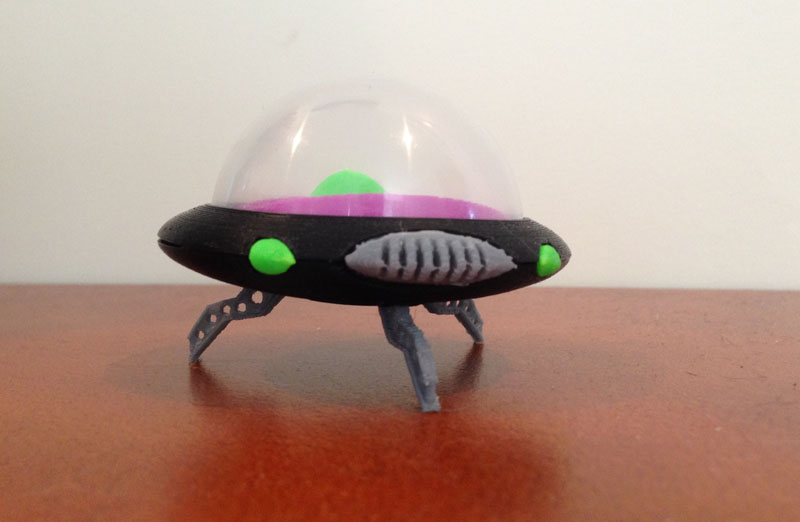
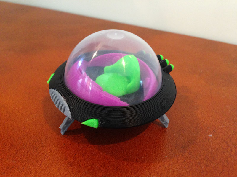
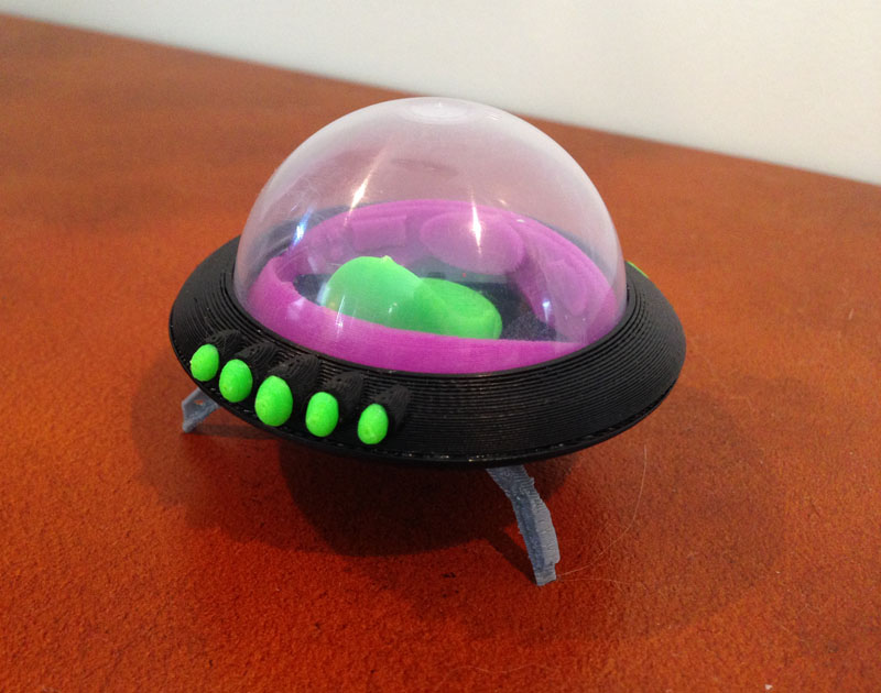
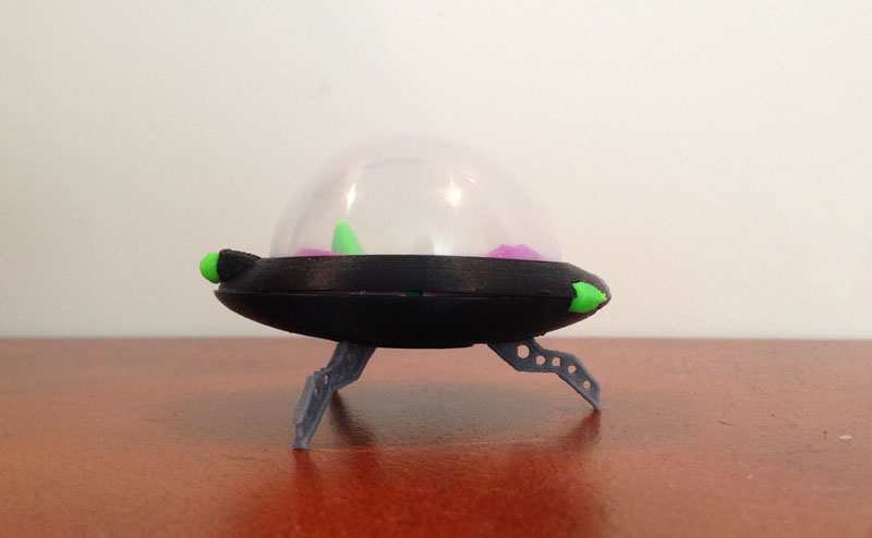
Cute Prototype
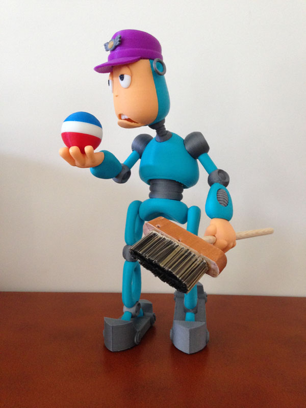
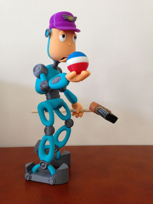
When I prototype, I use colors I normally have a lot of, but don’t use a lot of, like purple, pink, neon yellow, etc. In the first print of this model, I used purple and pink with green and white.
It was intended only for fit and to determine what issues the model would have.
But my daughter loved the color scheme and basically demanded it, so it’s now hers. Here it is.