My New Arduino

ArduinoUno_R3_Front_450px

A few years ago, along about the time I was investigating 3D printing through, mainly, MAKE Magazine, I found that there was this rather fast-growing phenomenon surrounding a small electronic circuitboard called the Arduino.

I was interested, of course, and read a few articles which often showed some rather advanced projects, and I thought, “That looks cool, but that’s far too advanced for me.”

But I kept reading and watching what was happening, and when Radio Shack started selling Arduinos in cool kits with bunches of LEDs, sensors and other electronics, I figured I should investigate further – perhaps even get one.

But I didn’t really understand what was going on.

But like I was when I got my first computer, the Commodore 64, I was sure I could learn it and make some cool projects.

Recently I bought an Arduino, a Raspberry Pi (another circuitboard, but this one is a fully networked small computer, including USB ports, an HDMI port, and ran Linux) and an Arduino Micro, which is a smaller version of the Arduino.

But what exactly is an Arduino? Not much of what I read told me what I wanted to know. Most of the articles I read assume some knowledge of the Arduino.

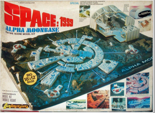
One interesting fact: It was invented in Italy by two men and named after a bar they liked. That’s when I realized the name was familiar.

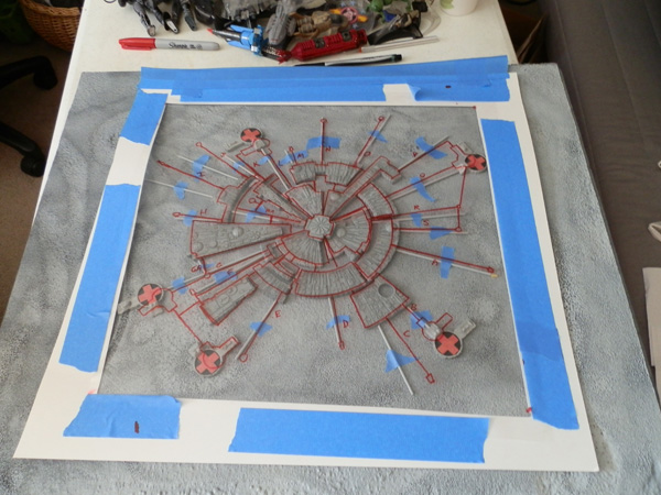
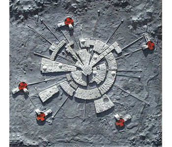
This poster has been hanging in my kitchen for nearly a decade. We bought it because it hangs in what used to be our favorite cafe in Norwood, MA. Here is that poster:

victoria-arduino-poster

So maybe it was destiny that I get bitten by the Arduino bug…

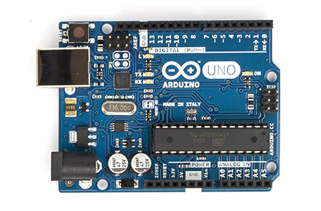
It turns out my initial understanding of the Arduino wasn’t far off – it is basically a computer on a chip that controls various input and output channels, and understands computer code. So if, for example, I want to turn an LED on whenever I push a button, I could simply wire a circuit up to a battery (which is a heck of a lot cheaper) or I could use my Arduino to wire up a switch, and whenever that switch turns on, have my code (which is fed to the Arduino through your computer connected by USB cable) turn the LED on. By hooking the switch up to an input pin, I can detect it, then when it turns on, use an output pin to turn on an LED.

My Arduino is the Uno, but I also bought a Micro, which is a very small version with most of the same functions.

ArduinoMicroFront_450px

(Shown here larger than actual size)

What it is, essentially, is a series of ports directly controllable through computer code uploaded to the board’s internal memory and run like a portable computer. Each pin hole does something useful and you can mix and match those to make rather complex projects.

It is so much more than that, though. With a potentiometer (variable resister, like a volume knob on a radio) I can read an analog signal, which converts to a number, and then I can feed that number out to an LED on an analog output pin and voila – the LED gets brighter as I turn the knob. Again, something most people could do with simple circuitry.

But because the Arduino understands computer code, I can do so much more. I can, if I want, use that potentiometer, and have an LED readout give the NUMBER the potentiometer is reading, through an LED display, or a row of LEDs like a bar graph – whatever my computer code can tell the output pins to do.

Suddenly the possibilities become exciting!

Over the last few days I have played with my Arduino just a bit, and got some interesting first findings, including how to blink or fade an LED (or multiple LEDs at different rates) using the various analog output pins. I also found several sensors that worked, like a pressure sensor (that turns on when you touch it) and others. I have so much more to learn.

But I intend to document some of that learning here.

I’ll start with my first project idea: A simple dice rolling program that displays its number in a way similar to how a 6 sided die works, with 3 LEDs down either side and a single LED in the middle.

Coming soon…

Thunderbird 1 – Take 2

Last year it was announced that WETA, who made all of the awesome designs for the Lord of the Rings and Hobbit movies, among other accomplishments, would be reviving the iconic TV series Thunderbirds, created by Gerry and Sylvia Anderson in 1964. The new series is going to be named after the first of two feature films the couple also made back in the day: Thunderbirds Are Go.

The first big teaser image from the show is the CGI model of the updated Thunderbird 1, seen here:

tag-tb1-cgi-model-01

It was soon followed by this image, almost the same, of Thunderbird 1 (TB1) flying inverted over the Hollywood sign:

tag-tb1-cgi-model-02

So I set out to model this and 3D print it using my Afinia H479 printer. (And my Afinia H480.)

Luckily, WETA has been touring around the toy and merchandising conventions with a large 10 foot physical model of the ship too, and some photos gave me more information about shape and proportion, as well as detail.

tag-tb1-physical-model-underside tag-tb1-physical-model-02 tag-tb1-physical-model-01

And of further help, a friend of mine, Barry Kay, took some very nice high-rez close-up detail shots from various angles all around the model, which I used to work out a lot of the detail. (I may post those later.)

The Parts

Here is a photo of all of the parts that make up this model. Note that there are 98 individual parts, including a display stand.

tag-tb1-3dprint-parts-all

The Main Body

The main body tube is made up of five separate parts. These parts comprise the main tube in silver, and two stripes in black mid-body.

Here, the top section has two underjets, and cutouts for the cockpit windows and body text which will inlay as white pieces.

Here the side text is inlaid, so that the TB1 reads upright from either side of the body (only one side shown here.)

tag-tb1-3dprint-body-side-text-inlaid-01

Then the topside of the body, which has the word THUNDERBIRD going down its entire length, is inserted, or at least the first few letters that are printed on this top section.

tag-tb1-3dprint-body-top-text-front-01

Then I do the same for the bottom body tube section:

tag-tb1-3dprint-body-bottom-text-01

Next I attach the five main section pieces including the sandwiched black/silver/black rings, which leaves a hole for the letter D:

tag-tb1-3dprint-body-main-assembled-missing-d

The Engine Section

The blue section of the body, if you look closely, is honeycombed with hexagons. This was the most difficult part of this model to make, but it was oh-so-satisfying when it printed so nicely. I cut the large number 1 from it and made that an inlaid piece, but with the honeycombing intact.

tag-tb1-3dprint-body-section-1

Here is an image someone posted of a texture used on this part of the body:

tag-tb1-cgi-body-detail

Here, I attach the large dark part, which looks like a heat sink, to the blue section. Note the detail on the bottom. This was not in any of the photos or CGI images I have seen.

tag-tb1-3dprint-body-rear-assembled

I got the detail from a rough GIF file someone posted of a turntable rendering of the ship that was on display on monitors next to the physical models at the conventions:

thunderbird-1

I snapped two frames of this GIF as it rotated and used them side-by-side to create a 3D parallax image (like a ViewMaster slide) and while the video has serious GIF dithering, I was able to make out some detail in depth, so I modeled in what I could see.

Next come the thruster housings for the 8 jet engines. Each housing has TB or TB1 (depending on which one) inlaid in, and two jet engines attached:

tag-tb1-3dprint-engine-housing-jets

Here are the four housings:

tag-tb1-3dprint-engine-housings-done

I had a conflict here. While the rotating turntable image (posted above) clearly shows the TB1 as upright on the upper and lower housings, so when the ship is landed flat it reads correctly, the physical model my friend photographed showed the TB1 as reading upright relative to the body, so I decided to go with the physical model for now.

(To make that a changeable thing, I opted not to glue the bottom thruster housing in place. It snaps in rather well, so it holds. Later, I will reprint that one with the TB1 facing the way it faces on the CGI model.)

Then I added the blue jet intakes to the tops of each thruster housing:

tag-tb1-3dprint-engine-housing-intake-attached

Then I added the housings to the heat sink section:

tag-tb1-3dprint-engine-housings-attached

Next I added the fins

tag-tb1-3dprint-fins-attached

Then the flare section that connects the engine section with the body section, adding the silver pins to the tops of the thruster intakes. (Note the display stand, which is not canon. I just made it interesting.)

tag-tb1-3dprint-body-bottom-assemby

I then joined the two body sections together.

tag-tb1-3dprint-mostly-done

Next are the main engine intakes, each made from 3 pieces:

tag-tb1-3dprint-engine-intakes

These get attached next to the slots where the wings would retract:

tag-tb1-3dprint-engine-intakes-assembly

Last Bits

Then I prepared the wings, which have tabs that fit into slots in the body shoulders.

tag-tb1-3dprint-wings

And here they are, slotted in place.

tag-tb1-3dprint-wings-assembled

(In a future version of this model, these wings will actually scissor out on gears, so they can retract, like they do on the show. But for now this will do. The wings on this model are static. Making them do what I hope to do later will be quite a complicated job, but one I hope to take on later this year.)

Almost the last part is the nose-cone:

tag-tb1-3dprint-fully-assembled-on-stand-topside

The very first image showing all of the parts has the window inlays printed in black. While I was assembling this model, I got a shipment with some glow-in-the-dark sky blue filament from Zen Toolworks, and I printed the windows again in that color to see if it worked better than black.

I also used a sample Zen sent me of translucent filament and tried that.

The winner was blue:

tag-tb1-3dprint-fully-assembled-on-stand-underside

So there you have it. My version of WETA’s Thunderbird 1 from Thunderbirds Are Go.

Here it is on display:

tag-tb1-3dprint-fully-assembled-on-display-underside tag-tb1-3dprint-fully-assembled-on-display-topside

Still missing: The Pitot tube which juts from the cockpit area, and some other body detailing, which I hope to add when I make the retractable-wing version later.


Look What I Made!

A week or so the folks at Afinia said they were looking for some solid single-print models so I adapted some of my stuff for them, some useful, some less so.

One thing everyone wants to print is a robot so I made them a seamless single print robot model which I gave them to do with as they please. They sent me some filament in return which made me happy.

Here is the little guy: at scale he stands almost exactly 10cm tall.

IMG_2875.JPG

IMG_2873.JPG

IMG_2874.JPG

IMG_2876.JPG

Our House – Is A Very Very Very Fine House

We are currently (as of Nov 28, 2014) in the process of purchasing a house. Here is a photo of the house in question:

our-house-actual-01

For as long as we have been able, starting in the late 1980s, Carol and I have collected the Hallmark House series of Christmas ornaments, with a couple of gaps here and there when we simply could not afford to buy that year’s house (mostly in the first 7 years). But mostly we have the whole set, and it goes on the tree every year, with new ones added.

This year Carol asked me to make her a Christmas Tree Ornament of our new house, which we hope is where we will spend Christmas this year.

Here it is. Well, here’s two actually, since my Mother requested one as well.

our-house-ornament-pair-01

The wreaths indicate Christmas. I also modeled green gift bows for the roof but I’m not sure I want to use them.

But in keeping with my last year’s ornament, the Afinia printer:

cropped-afinia-ornament-assortment-large1.jpg

… I think I will put this year’s date on the roof.

This picture is of the first of my 3D Printed Ornament Series which I created last year. I sent the files to Afinia, the makers of my printer (at their request after I sent them an actual ornament) and they printed it out in a number of colors and then used this image for their front page image for a while.

Big Hero 6 – Baymax

On Friday I took a sphere, popped a lattice onto it and warped it. I did the same again to a different sphere, and pushed one into the other. Then I did a third. Then a fourth, which I bent like a piece of macaroni. I duped that one 2 times and placed those by the original. Then I made another that looked a bit like a Vienna sausage. Then I made a conical cylinder. After putting those last bits together I duped it and mirrored it. I then made another sphere and warped it with another lattice and duped it.

Then I made two cylinders, scaled them a bit on the X and rotated them a bit, and created a low, wide cube. I duped one of the spheres, enlarged it a bit, and used Boolean to cut a hole in that sphere shaped like the cylinders and cube.

To top it off I made another sphere, extruded it a bit, cut a line through it and bent the line a bit, and shrank it down to fit the first sphere.

Then I used a series of booleans to combine these objects, and in some cases to cut holes, and this is the end result:

baymax-model

And here is the printed result, standing about 12cm high including base, or about 4.75 inches.

baymax-printed-01

Total modeling time, just over an hour.

Total printing time, about 8 hours.

As an added feature I made two hexagonal posts on the base that fit into two hexagonal holes in the feet so he can stand firmly on the display base, but he can also stand on his own, since his feet are flattened.

UPDATE – Nov 28, 2014

A day or two later I decided to position Baymax in a new pose – handing out a lolly-pop, as he is seen doing in the movie. Also I added his charging/docking station in open mode as a new form of display stand. I changed the angles of the left hand’s fingers so they print more consistently.

baymax-trio-01


The Bot Shoppe Has Two New Robots! – Introducing Poe-Bot and HP Hovercraft!

The Bot Shoppe now has two new members: Poe-Bot is based on Edgar Allan Poe and features a raven (“The Raven”, a trowl (“A Cask of Amontillado”), and his body is heartshaped (“The Telltale Heart”).

bot-poe-bot-01

And his companion, HP Hovercraft is a new body design. Sitting atop a hovercraft motion system, HP Hovercraft has six tentacles with which to work his horrors. The be-tentacled body spins!

bot-hp-hovercraft-01

This now the seventh robot in the Bot Shoppe.

bot-shoppe-lineup-2014-11-08

I Won! I Now Have Two 3D Printers!

A while back I posted that I had entered a contest at 3DAGOGO and won a Makerbot Digitizer, a 3D optical scanner. I was thrilled and I gave the machine several test runs. I was not overly happy with the resultant scans. I sold the scanner. I may get one later when the tech becomes something more reliable and accurate.

But that didn’t stop me from entering another contest. “What Would You Print?”

The idea was to submit useful, practical designs (by sending a printable file) and a panel would judge the winners based on practicality, usefulness and ease to print.

I submitted two designs that I came up with quite some time ago:

1) Grocery bag handles. One of the things I wanted to print with my printer even before I got one was a grocery bag holder that would help me carry more plastic grocery bags (and can handle cloth bags too) so my hands (which hurt when I carry too much weight with so little surface area) wouldn’t hurt when I carried groceries in from the car.

grocery-bag-handles-green-01

A simple design. Bag handles go into the slot, and you hold the handle. I find I can carry plenty of weight, but what the scrunched-up plastic handles do to my fingers makes the carrying much harder. This way there is no stress on my individual fingers, and I can carry double the weight in groceries per hand. The space is wide enough to accommodate cloth bag handles too.

2) A switch protector plate for the garbage disposal on our sink. The switch is under a cabinet and is hard to see unless you lean down. There are two switches on a common plate and I can’t count the number of times I turned on the disposal when I intended to turn on the light. So this plate now sits over the disposal switch and makes it impossible to turn on the disposal by accident. You have to slide your finger in between the two guard rails to use it.

switch-protector-red-01

You simply remove the two screws, place this plate directly over the switch you want to protect, and screw the screws directly back in place. No expertise needed. And now to use the switch you have to be very deliberate. You simply cannot accidentally turn on the disposal.

Apparently both of my entries were in contention for a prize. This video announced the entries.

Then I got an e-mail congratulating me on winning second prize – a RioTBoard, which is a circuit project board that allows you to make any number of electronic projects. I was reasonably excited. I began to look forward to trying out some projects.

Not long after that I got an e-mail apologizing. They claimed they got the e-mails mixed up. Apparently I had not won second prize, I had won First Prize!

I had actually won Grand Prize which was an Afinia H480 printer!

The Afinia H480 is the next model up from my own Afinia H479 printer which I have had for a year and a half and have loved since I got it.

The Afinia H480 is essentially the same printer with some extra features including a print bed with springs to hold down a print plate, and an auto-calibration system.

With the Afinia H479 you calibrate the board by rotating three set screws holding the plate in place. You use the Mainenance Panel in the software to raise the print bed up to meet the nozzle and leave .2mm of room between the nozzle and the plate in all four corners and the center. When you can slip a standard file note card under the nozzle cleanly (not too tight, but you can feel the drag on the nozzle) you have calibrated the bed.

I find calibration stays set for quite some time. A knock or an accidental print incident that moves the bed could pull it out of calibration, but it’s not something you have to do daily, or even weekly, usually.

But if you want to ensure a good calibration, the H480 allows you to attach a calibration switch to the print head and use the software to level the bed and detect nozzle height. Note that this appears to be a software leveler. It does not level the bed, it just detects the tilt of the bed and prints to that angle, I believe.

Watch this video from 1:30 onward to see how the calibration and nozzle height detection works.

But I can’t tell you how thrilled I was to find I had won another Afinia printer. I sometimes do projects that require a lot of printing and being able to have two running at once will really cut down my print times on larger print runs.

MPC / fundimensions Revised Moonbase Alpha Model Kit

How I envied my friend back in the 1970s when he got the model kit of Moonbase Alpha from the TV series Space:1999. It featured a moon diorama base with the radial iconic Moonase Alpha, with three Eagle Launch Pads, six miniature Eagles and as a bonus, a larger model of the Main Mission room complete with tiny figures.

moonase-alpha-original-kit-box-cover

Some years ago, AMT/ERTL reproduced the kit, fairly accurately, but notoriously with a vacuum-formed base that was not very good. The tubes leading out to the launch pads were molded into the base and badly defined, and the launch pads themselves had issues: they were too large (by 20%) and there were only 3 of them when there should be 5. This meant that the tubes were incomplete, since the pads needed to be connected to base by transport tubes.

moonbase-alpha-ertl-repro-kit-cover

Nonetheless I snapped up a copy of that repro kit for later construction.

I decided the base itself was not going to cut it, and what I ultimately wanted to do was make a square, framed wall hanging of this moonbase to hang on my wall.

Last year I took it upon myself to take the moonbase parts (the base itself is not bad) and make my own lunar landscape, lay down the moonbase, then use coat hanger wire (the only thing I could find to scale – but heavy) and 3D print smaller launch pads, and lay out a very accurate Moonbase Alpha.

layout-to-scale-I-hope

I cut a 50cm x 50cm piece of styrofoam pink insulation sheeting (a go-to favorite for project work) and spray-painted it. Spray-paint eats away at styrofoam, so the result was a rough lunar landscape with craters and mountains carefully sprayed in. Then I used craft paint with a roller to paint it and cover the pink pock-marks I made with the spraypaint.

Here is the rough layout before I put the transport tubes in place:

OLYMPUS DIGITAL CAMERA

The Alpha Moonbase patch was to be part of the display.

I began this project before I got a 3D printer, so the first thing I had to do was create two more launch pads or buy them. I bought some molding putty and epoxy resin and molded and cast a few pads:

OLYMPUS DIGITAL CAMERA

I printed the landing crosses on a color laser and glued them down. Not a stellar casting job…

I also needed more pips, the housings that terminate and join the transport tubes, since the kit did not come with enough:

OLYMPUS DIGITAL CAMERA

I printed this diagram out on several sheets, taped it together in scale, then used a piece of plastic over it, drew out the tube layout and base placement, and taped this to my lunar base for layout, just test-fitting the pieces on the layout:

OLYMPUS DIGITAL CAMERA

I was about to glue everything down when I got my 3D printer and decided to scrap the cast bases and model my own at true scale, complete with docking tubes (a piece missing from the originals) and re-lay it out again with minor changes needed to adjust the scale.

First, I reproduced the original launch pad, adding the docking tube, at original wrong scale:

OLYMPUS DIGITAL CAMERA

Later, I printed several of them at 80%, which is closer to accurate.

I was preparing those when I noticed that my styrofoam layout had been attacked by one or more of my three cats.

willow-wanda-rowan-3

Oh, sure, they look all nice and peaceful and harmless lying there… but believe me, they are vicious diorama killers!

So I gave up on the project, it being winter now, and I had no way to recreate the moonbase effectively. Spray painting outside in winter is not a great activity. I gave up the project.

But then AMT/fundimensions go and announce they are again reproducing the original Moonbase Alpha kit – only get this:

This time they are producing it properly! The lunar base diorama will be more accurate, better and easier to assemble, fit together properly, and would not have the transport tubes molded in.

They would provide transport tubes to lay out.

mpc803-4

They would give us 5 launch pads, not 3, and at proper scale, with docking tubes! As well as the originals for those who wanted to reproduce the original inaccurate model kit.

mpc803-5

They would remove the Main Mission component from the layout and make it a stand-alone section of the model kit.

mpc803-2

They would give us not only the original overscaled Eagles, but six new properly-scaled Eagles as well!

round2-kit-parts

And this whole kit would cost under $40.00. Did I fall asleep and dream this?

NO!

It arrived two days ago! I will be spending some of this fall building it, and framing it when I’m finished. More as news develops!