The Bot Shoppe – More Bots

I’ve shown you the first two robots in my Bot Shoppe, Tread-Bot and Grab-Bot:

bot-shoppe-tread-bot-grab-bot

Since I created these two, I have doubled the ranks with Sentry-Bot, a fast-moving motion sensor whose entire job is to patrol at high speed (with wheels that move him in any direction) and to alert authorities.

sentry-bot-02

And introducing Shakes-Bot, a robot bard whose entire job is to write awesome stuff.

shakes-bot-04

And just today I’m introducing Push-Bot, a sturdy industrial pushing robot. (He may know the Terrible Secret of Space!)

Here is the 3D model. He has not yet been fully printed. I have changed just one or two details since this model, so when I have a printed version, I will post it here.

push-bot-3d model

And here is the first glorious print. I added a head comb that, if it were functional, would light up like a forklift when it’s in operation, flashing.

push-bot-01 push-bot-02

AT Set 4: Save The Endangered Pygmy Rhino

Overview

With Set One done, (Adventure Team Action Pack Flight Pack), Set Two done, (Adventure Team Remote Drone Surveillance), and Set Three done (Adventure Team Action Pack Backpack Drone Surveillance) I set my mind to a third set that would harken back to the iconic Adventure Team days.

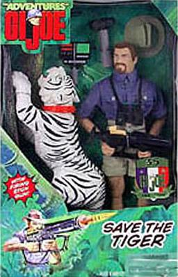
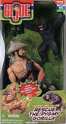
You may recall that one of the Adventure Team’s main activities was conservation. If Joe wasn’t searching for a Pygmy Gorilla or a White Tiger, he was after the Abominable Snowman.

Admittedly, in the 1970s, he was sometimes hunting these things, but in modern times, it was clearly “Save the White Tiger” and “Rescue the Pygmy Gorilla”.

One of today’s most endangered species is the White Rhinoceros. Many rhinoceros species are hunted for nothing more than their horn, and that demand comes from superstitious idiots who think that ground up rhino horn is useful for aphrodisiacs and medicinal application. It is not. Poachers kill rhinos for no good reason. They kill tigers for the same reasons. The fact is they do it because the creatures are rare. If there was one unicorn in the world, some fuckwad out there would be hunting for it because its horn would cure gout.

One way to save rhinos is to remove their value to poachers. How? Well, it’s a bit controversial, but hey, this is the Adventure Team, so I figured that the Adventure Team’s goal would be to find rhinos in the wild, track them, tranquilize them, perform a surgical removal of the horn and the rhino would walk away relatively unharmed. But rhinos have need of their horns for digging and defense. So instead of just removing the horn, I figured the Adventure Team would replace the horn with a prosthetic. But not just any prosthetic. This one would have a panoramic camera which would record any attempt to kill them, with satellite uplink to track them and should harm come to them, video of the last hour would be uploaded to AT HQ and the poachers could be hunted down and prosecuted.

The Rhino

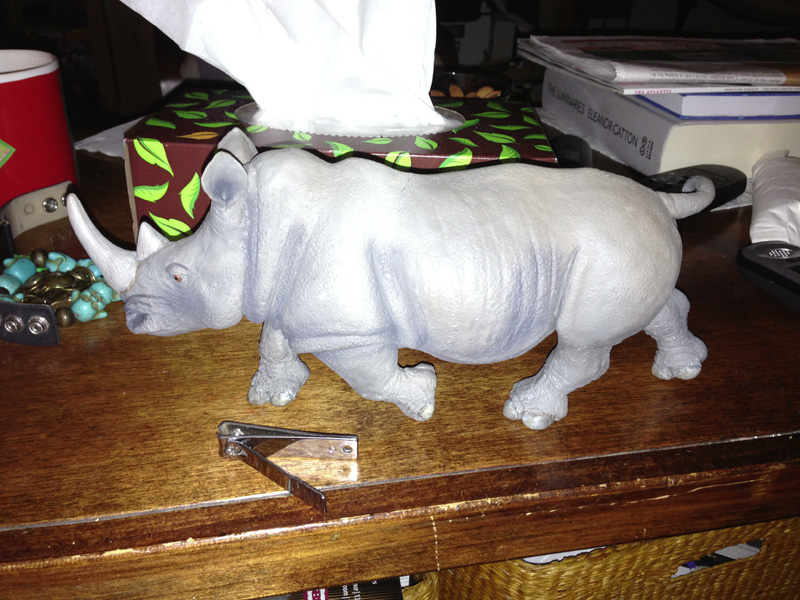
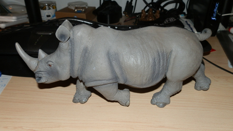
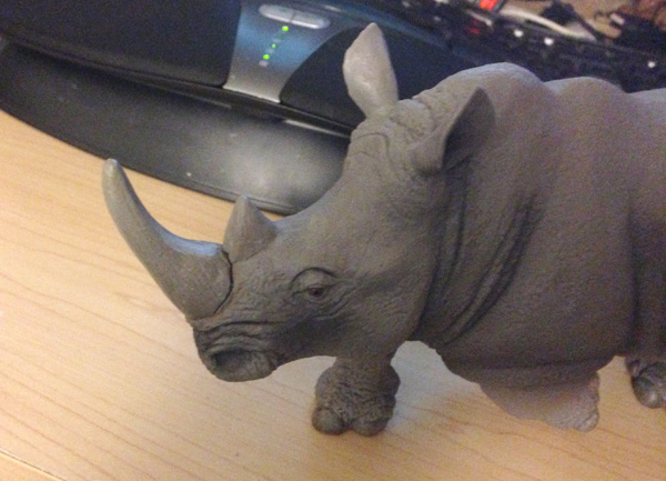
To that end, I first scoured the internet for a suitably-sized rhinoceros. There were a few on eBay, including a Big Jim one, but these were all too small. I found, thanks to some fellow collectors, a great Rhino from Safari Ltd, Wildlife Wonders line. I got it on Amazon for under twelve bucks, and was thrilled when it arrived. Very detailed, very accurate, and nicely scaled.  He is more than a foot long from tip to tail, just about big enough for a small-ish 1:6 scale Rhino. So, again going back to old GI Joe days, I’ll call it Save the Endangered Pygmy Rhino.rhino-new

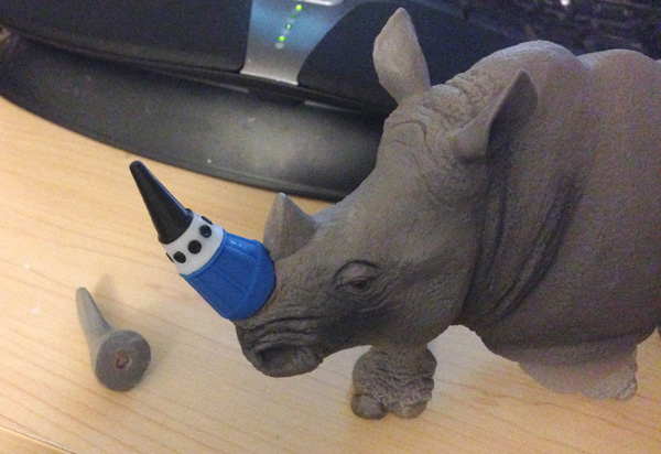
So I immediately removed its horn with a sharp knife. It was soft rubber, so it wasn’t hard. And then I figured I would use some of my rare earth magnets, one in the horn and one in the nose of the rhino. But my magnets are either way too small, or a bit too big. So I ordered some cylindrical ones online and they arrived about a week later and I used a drill bit to drill out spaces of appropriate size and inserted magnets.

OLYMPUS DIGITAL CAMERA

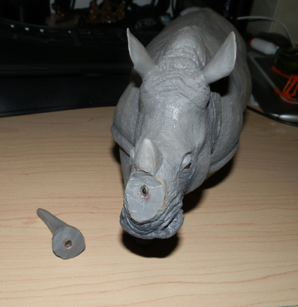
Now the horn can be reattached almost without noticing it was ever cut off. And when Joe removes the horn, he can apply the prosthetic using another magnet. Of course the fiction is it was surgically removed, and the prosthetic applied and sealed surgically for a solid join that would make the prosthetic as strong as the original.

OLYMPUS DIGITAL CAMERA

So the set has a rhino. Now what?

Surveillance Drone

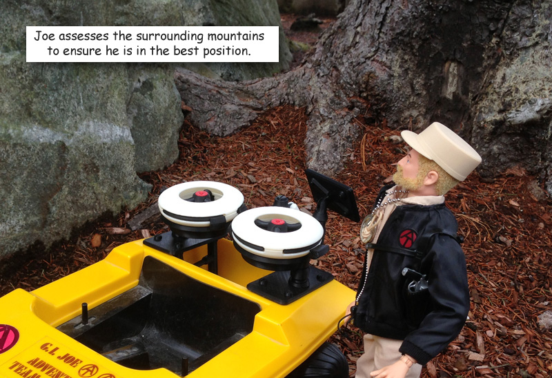
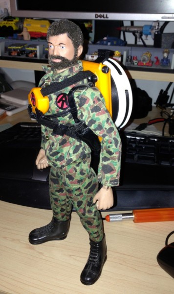
I needed something to track the rhino. Great. I just completed Set 3: the Adventure Team Action Pack Backpack Drone Surveillance. Clearly this backpack would be ideal. Using a remote drone to track the rhinos would be perfect.

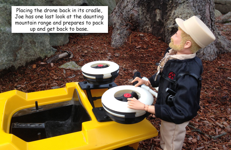
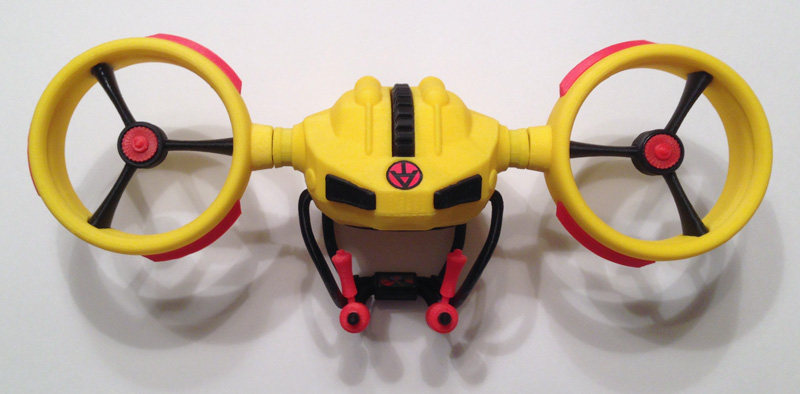
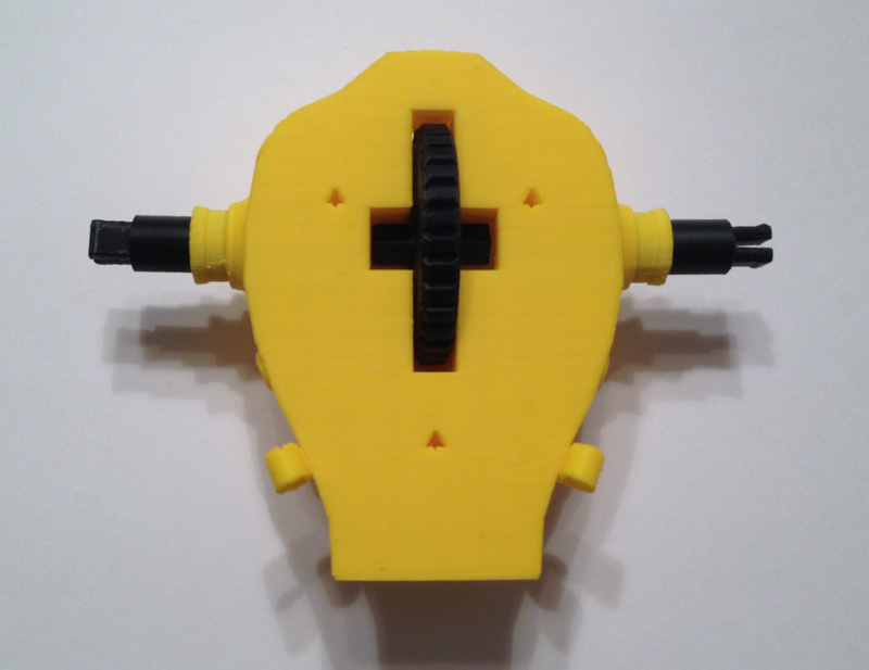
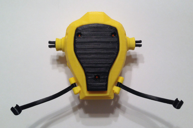
The drone is meant to be carried on a backpack:

at-drone-backpack-worn

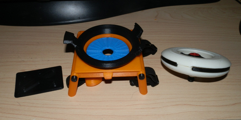
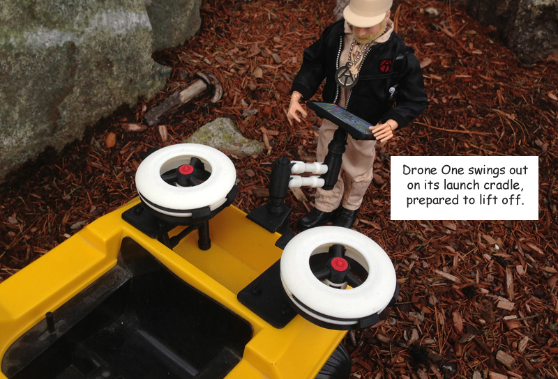
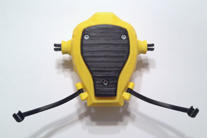
Removed, the backpack has four legs that fold down to form a launch pad:at-drone-backpack-launching

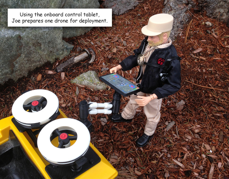
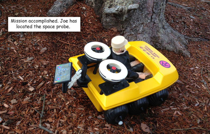
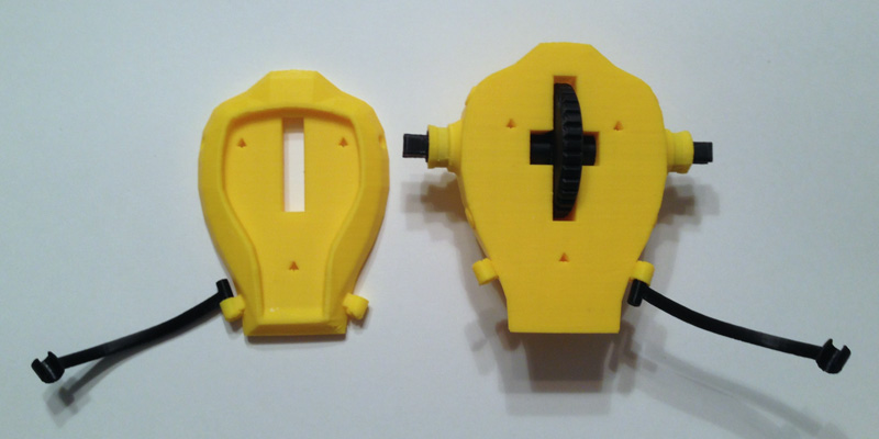
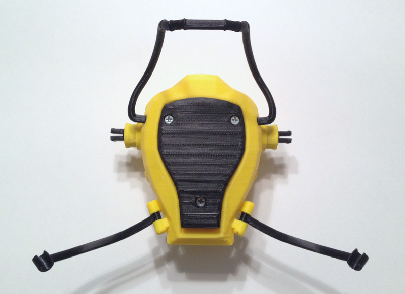
The backpack’s back part stores a control tablet:OLYMPUS DIGITAL CAMERA

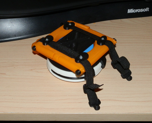
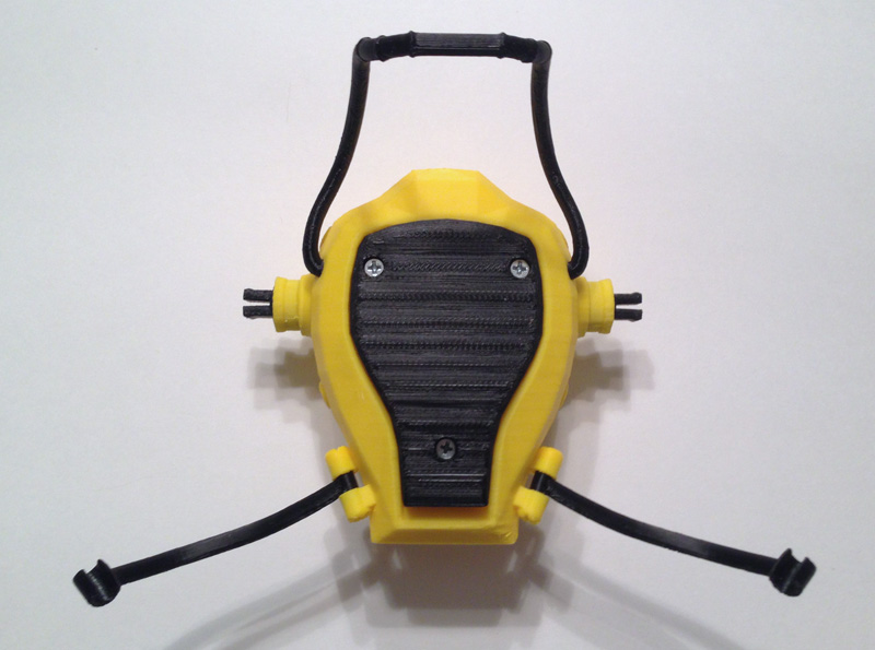
Which stores behind the elastic straps in a small notch shaped specifically to hold it:OLYMPUS DIGITAL CAMERA

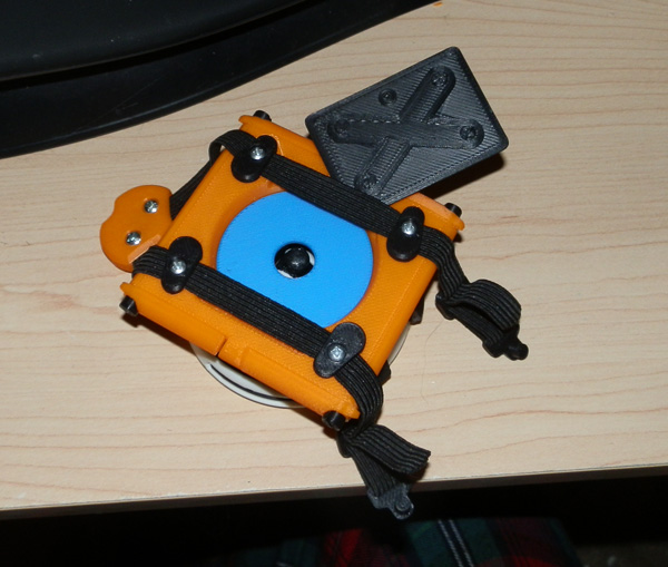
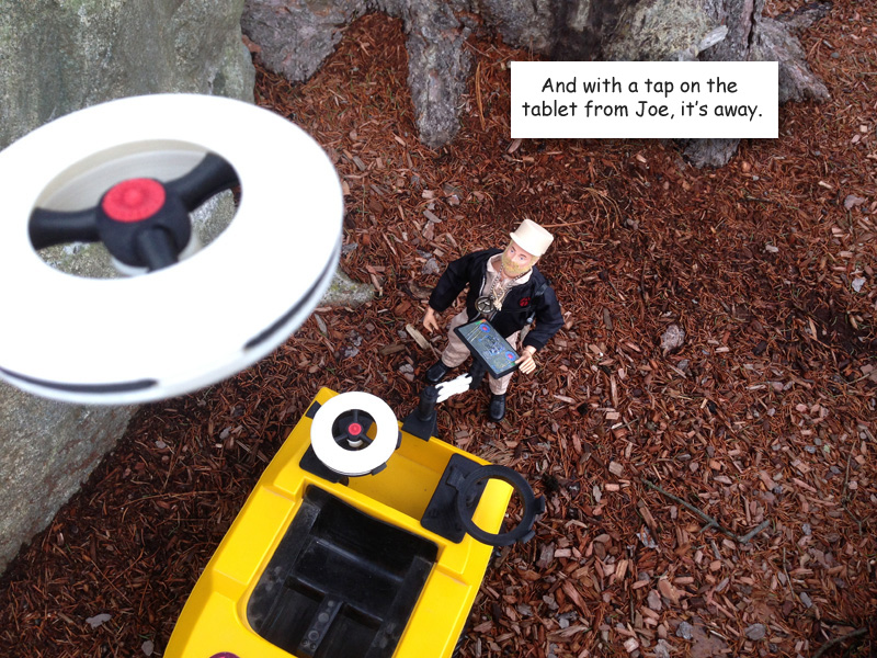
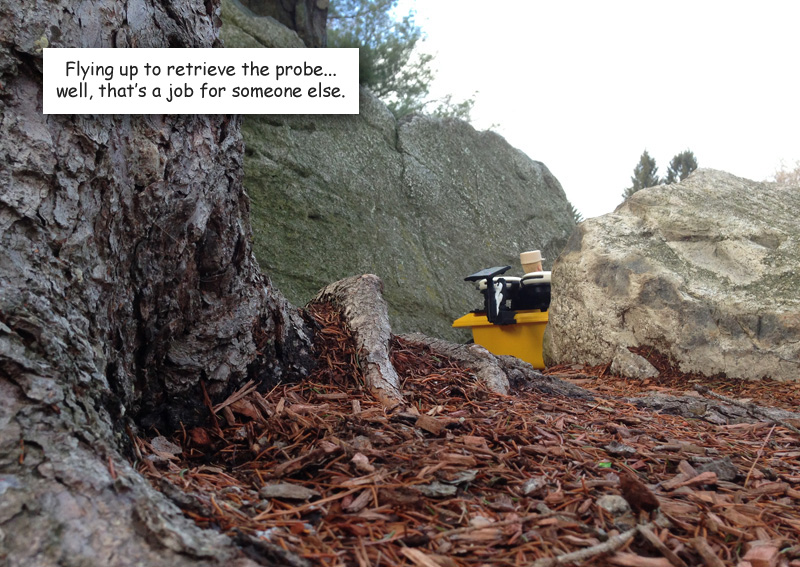
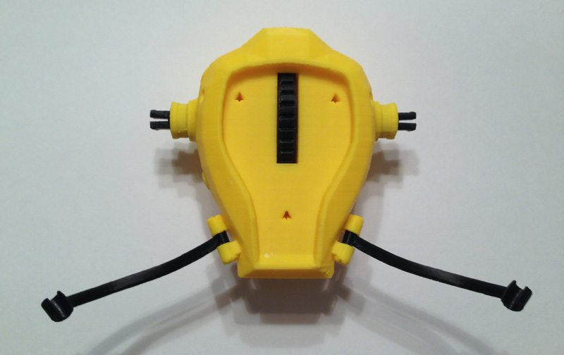
When the drone is launched, it exposes a solar cell which powers up internal batteries to keep the drone charged:OLYMPUS DIGITAL CAMERA

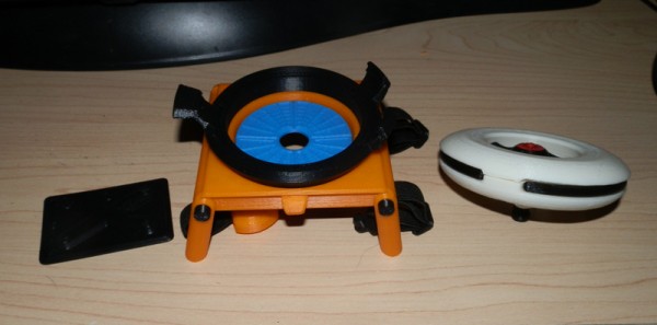
Taking Down A Rhino – Safely and Harmlessly – Tranquilizing Darts

The set will also include a tranquilizing bazooka with six tranq darts, an ammo case to store the six darts, a surgical sealant gun, a bone saw, and of course a prosthetic horn with magnet to replace the beast’s real horn. I also have a nice Soldiers of the World set of surgical instruments, and will likely include that as well.

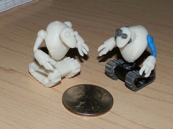
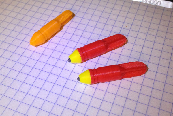
So far I have two tranq darts printed. These were prototypes, but I don’t think they need any changes. I will just print some more to make up six.

rhino-tranq-dart-full-color-parts
This photo shows the orange prototype, then the first test-print in color. You see two bodies, two heads and the two tranq injector tips, which use a spray-like injection system, not a needle.

rhino-tranq-dart-full-colorHere are two completed.

I designed them to be 1cm in diameter, and that will perfectly fit the bazooka that comes with the GI Joe Collectors’ Club Convention Set: “Search for the Sasquatch”. That bazooka “fires” net rounds that blow up and a capture net comes out.

rhino-tranq-dart-test-print
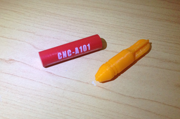
Here’s one of the Convention Set’s net rounds next to my orange prototype print.
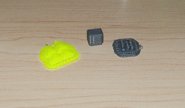
Ammo Box

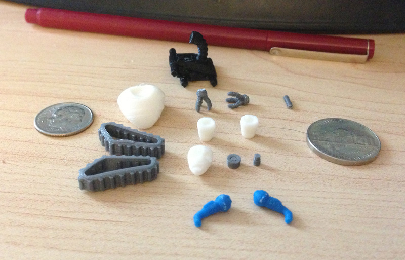
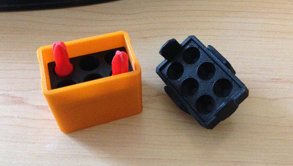
Here are the first pics of the Ammo box. It is a hefty, armored box designed to hold six tranquilizing rounds.

at-rhino-ammo-box-parts
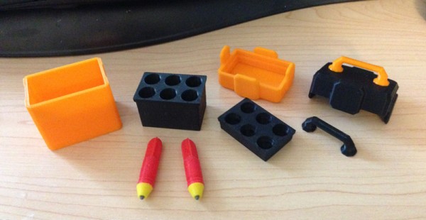
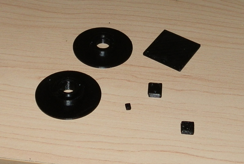
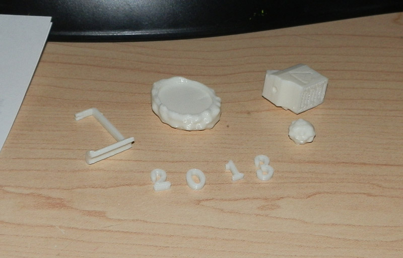
This is the box frame, the box insert which holds six rounds, then an orange version of the box top with upper insert, a black version of the box top (with orange handle in place), a black handle (should I opt to use an orange top instead) and two rounds.

at-rhino-ammo-box-open-02
Here, the inserts are placed in their box shells, and two rounds are placed, fins-up, into the protective packing.at-rhino-ammo-box-open
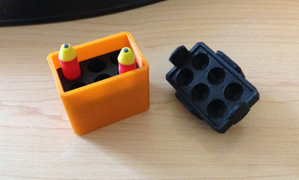
Same  box but with rounds point-up. I wonder if this doesn’t look better. Doesn’t matter, though, because it fits either way, leaving it up to the kid, if this were a real production set.

at-rhino-ammo-box-closed
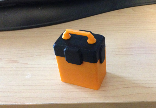
And this is the box, closed, using the black top. I think the black works better. Soon, an AT logo will be applied to the box front.

Note that the box is flat-bottomed. I’m planning a second print that has a beveled bottom just like the lid.
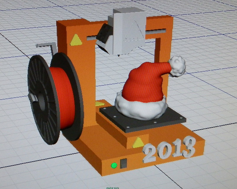
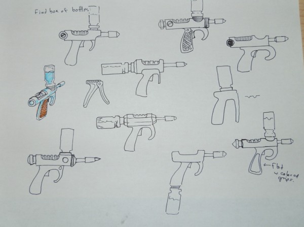
Concept Sketches

I sketched out some of the parts for the set and decided to let people see it. I don’t normally post concepts or early sketches, but I thought this would kind of force me to stick to these ideas, rather than go wildly off-plan when I’m modeling.

Note: Things will change, surely, while I’m modeling, but hopefully what I end up with will remain fairly faithful to this. The box and darts were actually sketched after modeling, so they will be pretty accurate.

at-rhino-concept

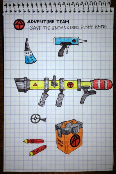
What you’re seeing is concept for the prosthetic rhino horn which has at its base a solar cell, and in the middle a panoramic web cam, and at the top, a satellite uplink antenna/GPS unit.

To the right is a sealant gun. It’s like a caulking gun but with surgical sealant to ensure the horn stays on even during the roughest rhino behavior.

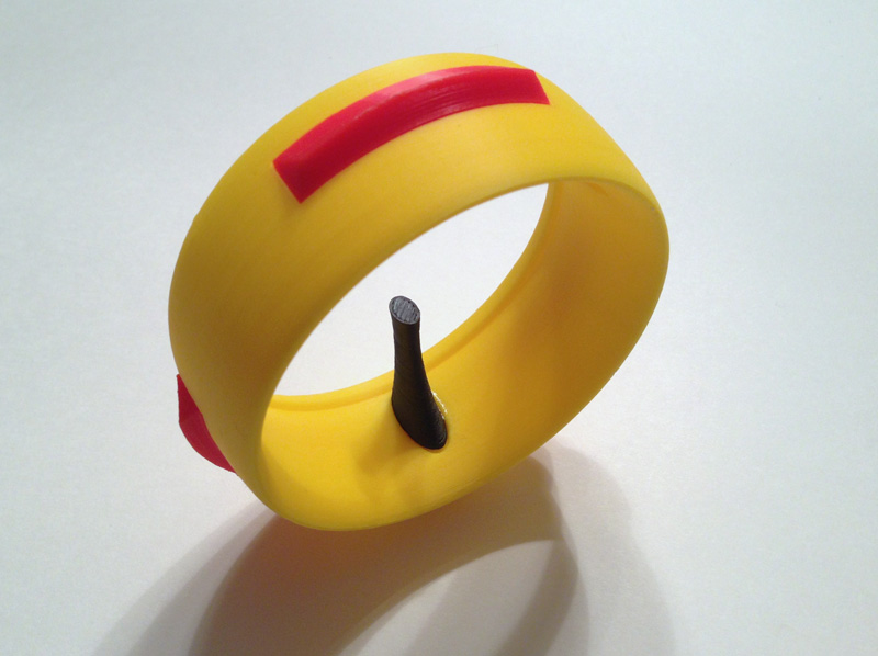
Air-Powered Tranquilizing Bazooka

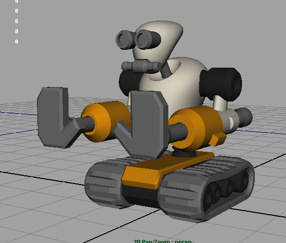
The main event, you might say, is the air-powered bazooka. It will be a hollow tube for the darts to fit in, and my current plan is for the two pistol grips to be rotatable so Joe can rotate them to a comfortable fit. The target sight is either going to be a traditional cross-hair, or more likely a video screen. The red canister at the back is a compressed air tank.

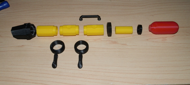
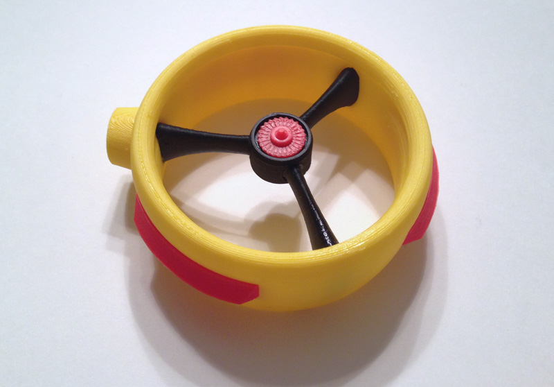
Here is the Tranq Bazooka in pieces. This is a first attempt. I modeled and printed this in one evening, and it is not complete. It was a test for fit and concept.
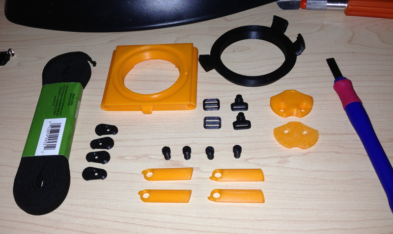
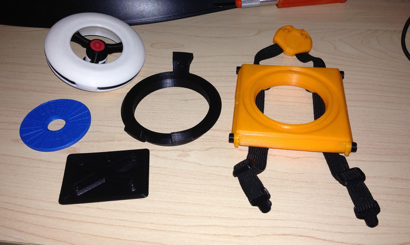
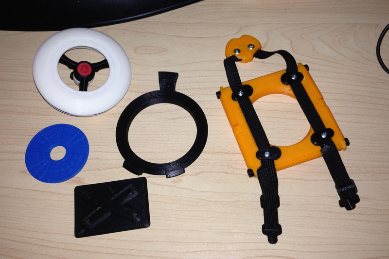
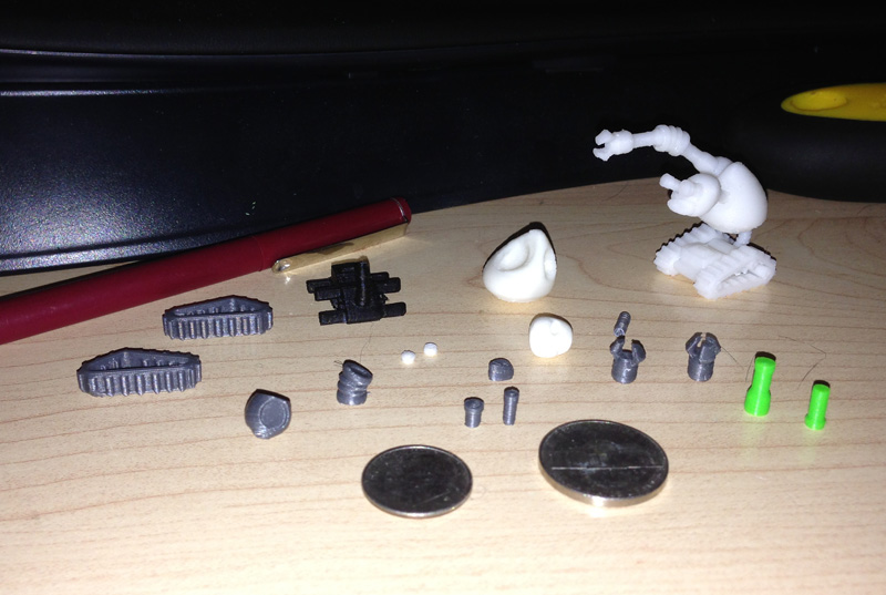
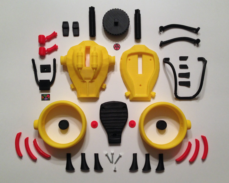
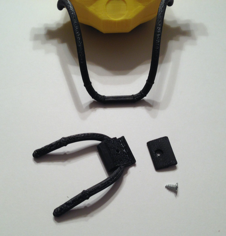
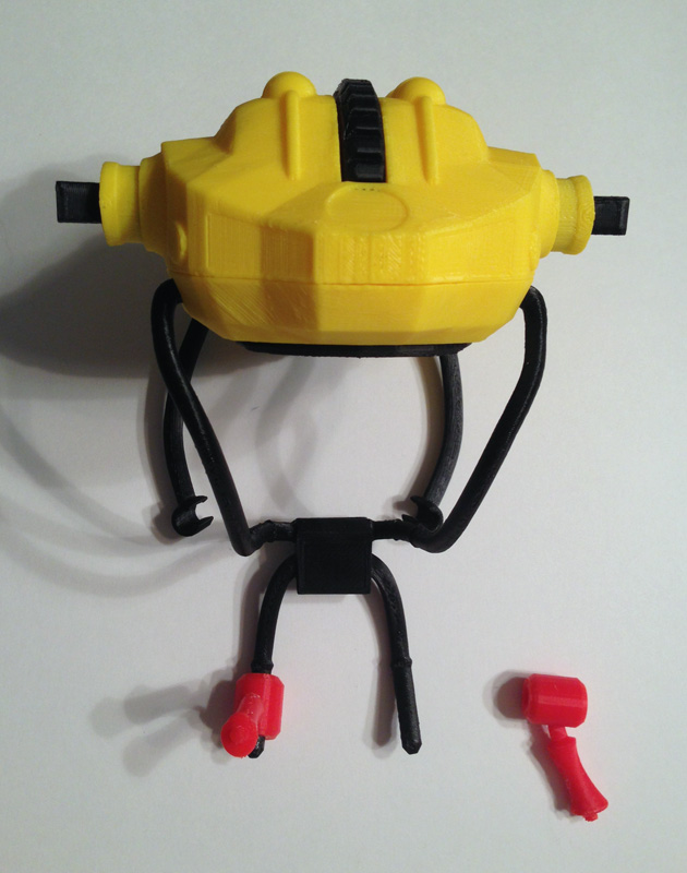
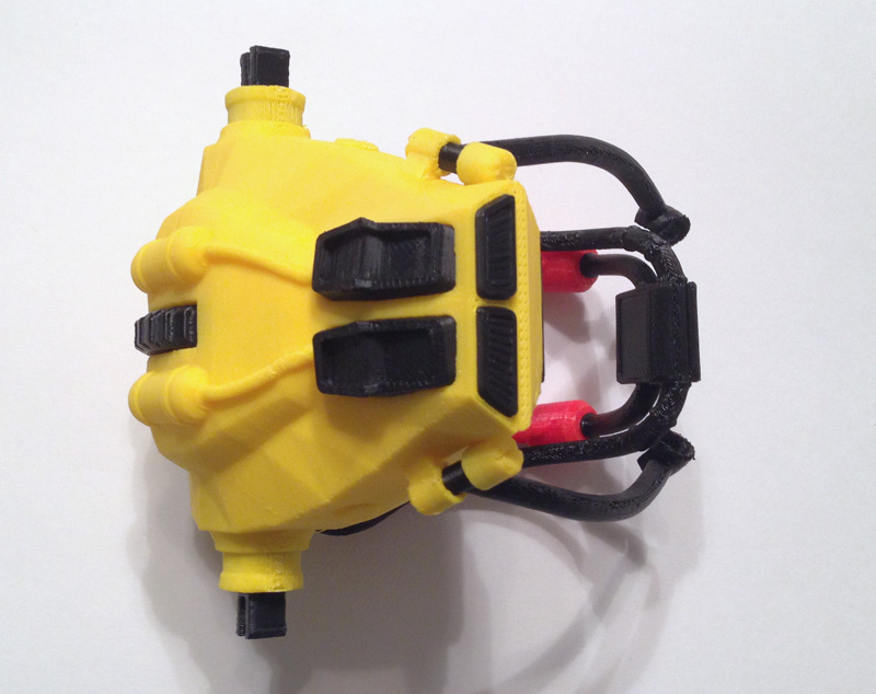
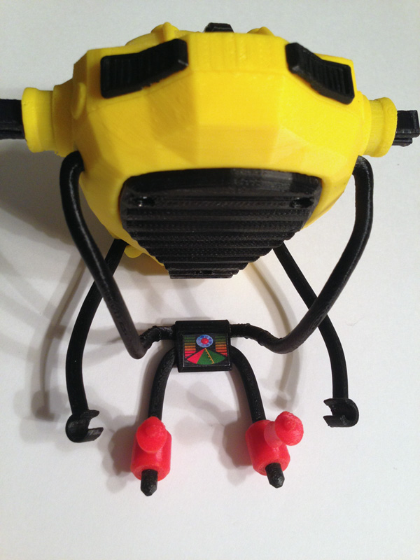
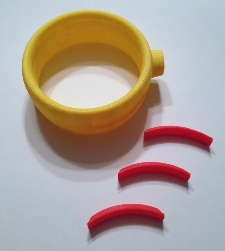
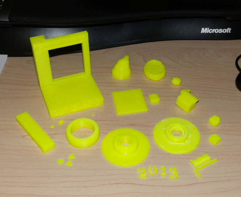
Here are the parts:OLYMPUS DIGITAL CAMERA

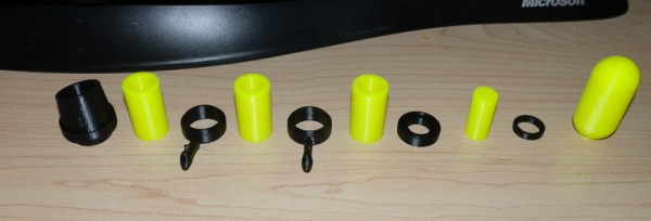
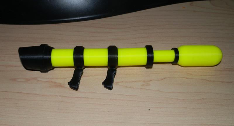
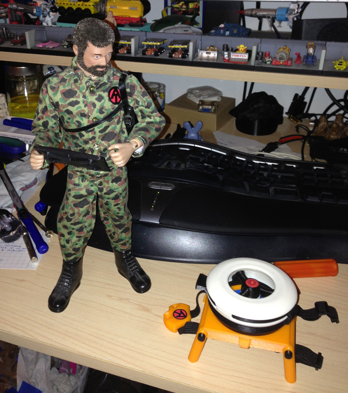
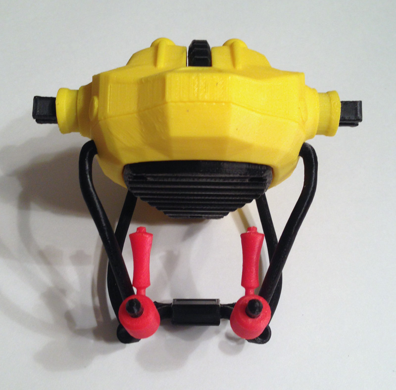
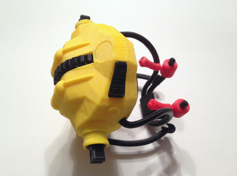
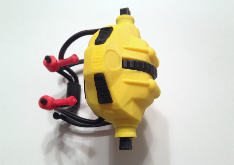
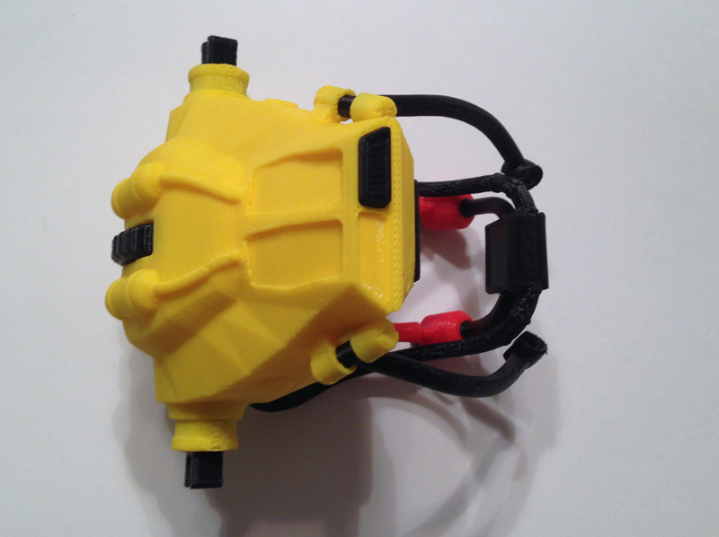
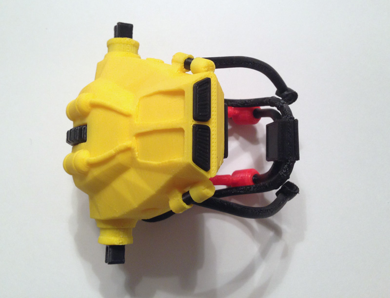
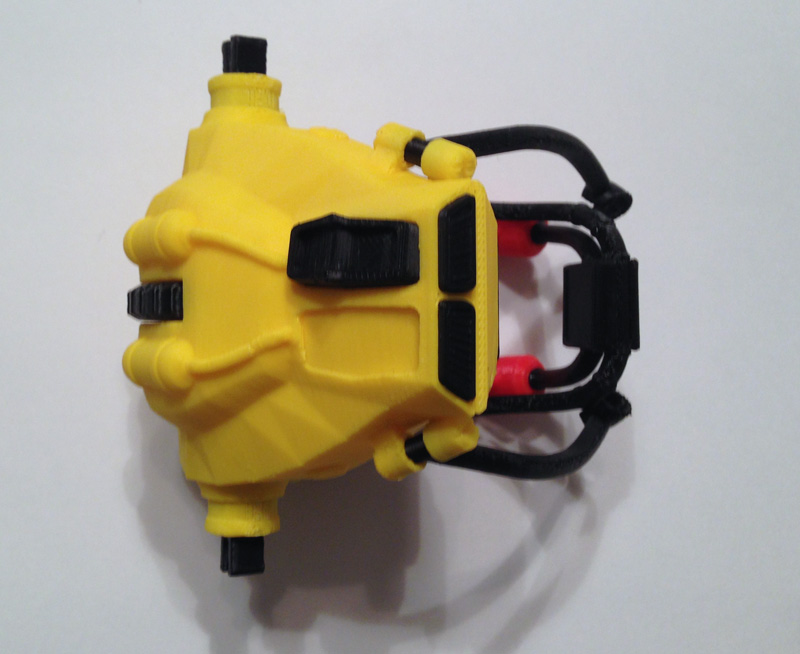
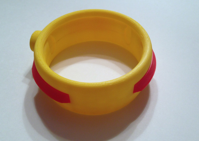
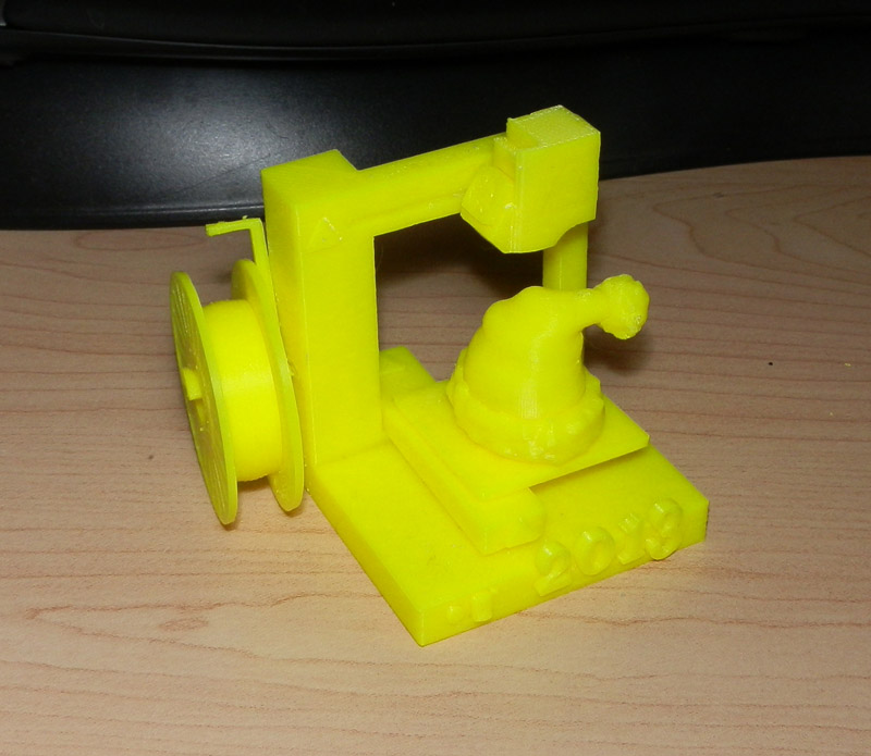
Here is the bazooka, assembled:OLYMPUS DIGITAL CAMERA

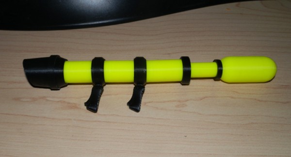
Note that hi-vis yellow is a color I use to test-print. But I actually like it. I am not sure I’ll keep it. The next print will be in AT yellow and I’ll decide which I like better.

The gas canister is supposed to be red, but again, this is just a test print.

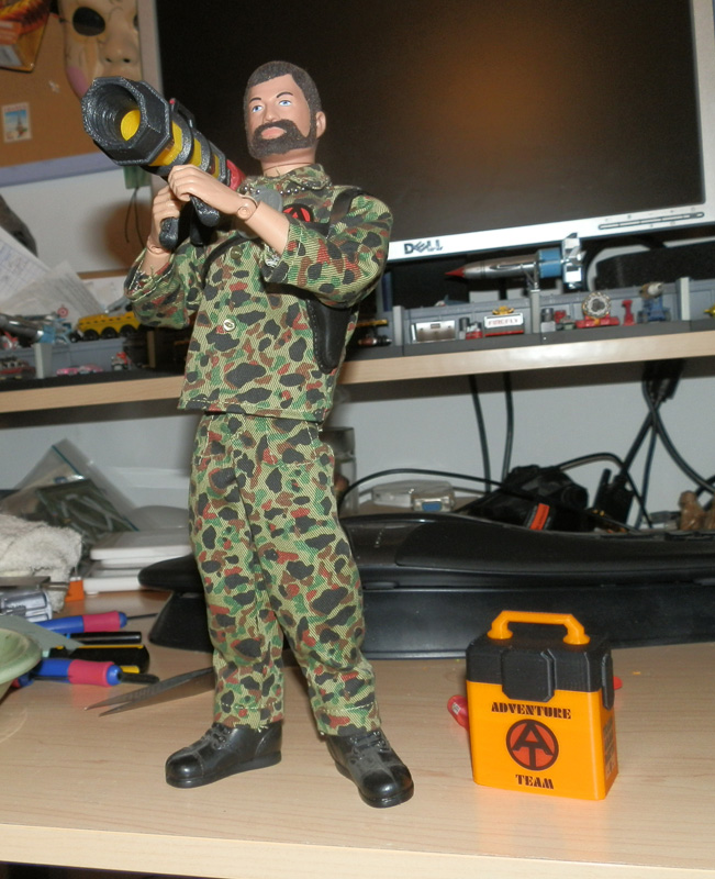
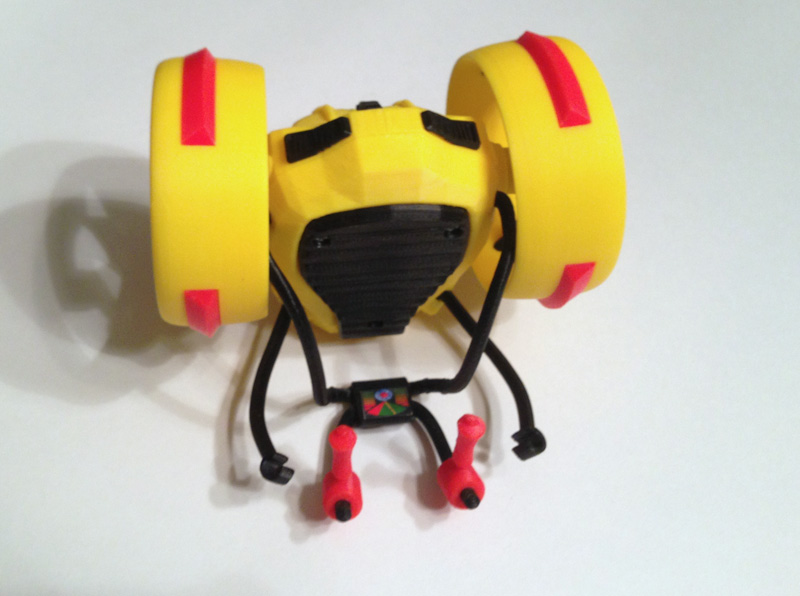
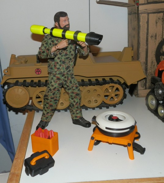
Here, the Land Adventurer is aiming it:
OLYMPUS DIGITAL CAMERA

When I saw the test print I thought it was ok. But I felt I could add some character to it.

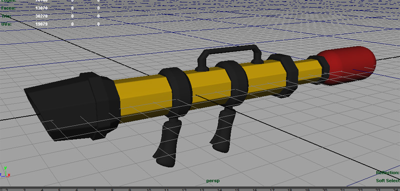
I decided to change the whole design to an octagonal shape, and here is the 3D model of the redesigned version:at-rhino-tranq-bazooka-3d-model-take-2

Note that it does not have a sight system yet. That’s coming. And some other detail may be added. I also added a carry handle which is in fact the same handle the ammo box uses, slightly altered to fit the bazooka.

If this print works well, I will be making additions including a way for the two pistol grips to rotate. I found that if the two grips were vertically aligned as you see in the 3D model, it’s harder for Joe to hold. So I wanted to angle the forward one outward for a more comfortable hold.

I also don’t want grips that are permanently angled, since I hope to also include a storage crate. My original concept sketch doesn’t show it, but I always intended for the grips to rotate. The photo of Joe holding the bazooka shows this. However, I want to limit the range of rotation. I don’t want you to be able to rotate the handle all the way around. So I am going to try to put in a peg/slot system into the barrel and the handle ring so that it can rotate outward to a maximum on either side, and then back to center for storage.

This may not be necessary and will complicate the model a bit, but I think if I decide it’s necessary it won’t be too hard to do.

Here is the first print of the second version, which has an octagonal outer body:

OLYMPUS DIGITAL CAMERA

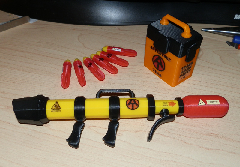
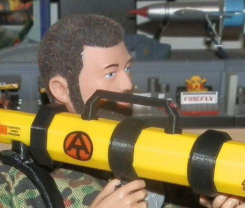
Here you see the bazooka, completed, with decals. These are water-slide decals printed on my laser printer, cut and slid into place. I’m not sure the ones on white “paper” are sticking well, but the clear ones seem to be.

OLYMPUS DIGITAL CAMERA

On the left is an explosive warning, then there’s an AT logo, a “Contents Under Pressure” with a red arrow. Then the gas cylinder has a pressure warning triangle, with “Compressed CO2 Gas” in text.

The darts themselves say “Caution Etorphine”, which is an animal tranquilizer for large animals.

The box, you can see, has the AT log with Adventure Team, and “Tranq Ammo Darts – 6 -“.

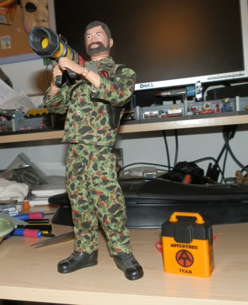
Here you see the Land Adventurer aiming the bazooka:

OLYMPUS DIGITAL CAMERA

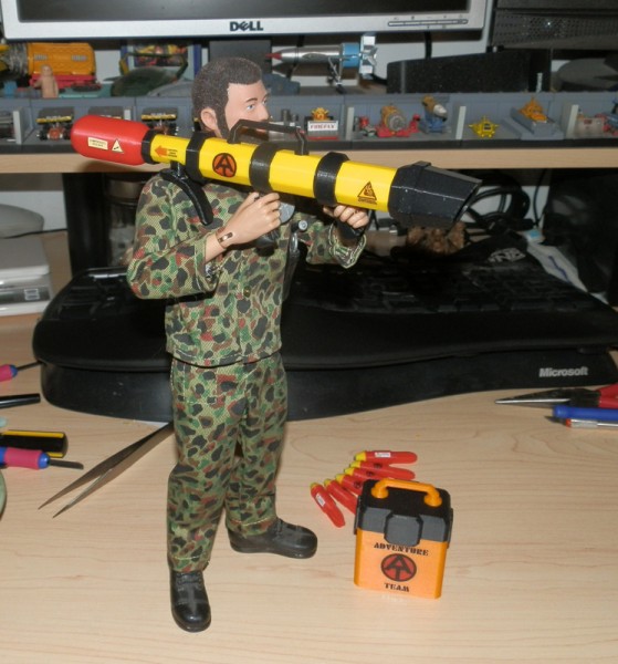
Note the new detail I added – a very small but noticeable laser sight. The small red dot is 1mm in diameter, and it printed fairly well. The hole in the handle printed nicely too. I was a bit surprised, considering the scale.

OLYMPUS DIGITAL CAMERA

One feature I built in was the ability for both handles to swing out for a more comfortable grip, which you can see better in the following picture:

OLYMPUS DIGITAL CAMERA

Next: Sealant Gun

Here is a new concept for the Sealant Gun. Instead of using what, in my original concept above, a caulking gun, I figured this should be higher-tech. I had purchased these small glass vials for Steampunk gun (full sized) customizations. I bought a lot of them. I think it was a 100 count from China.

OLYMPUS DIGITAL CAMERA

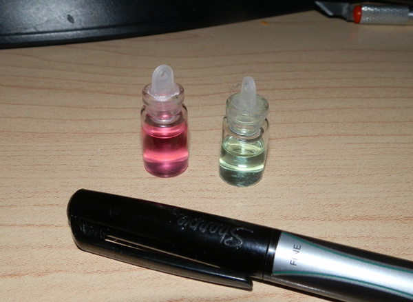
Here you can see them filled with two types of mouthwash for color.

So I figured how perfect would it be to use these for the sealant gun and make them a much more high-tech device that would resemble a lot of the injector guns you see in science fiction TV and film.

So I began sketching.

OLYMPUS DIGITAL CAMERA

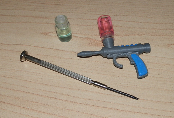
I modeled one up fairly quickly and test-printed it in silver.OLYMPUS DIGITAL CAMERA

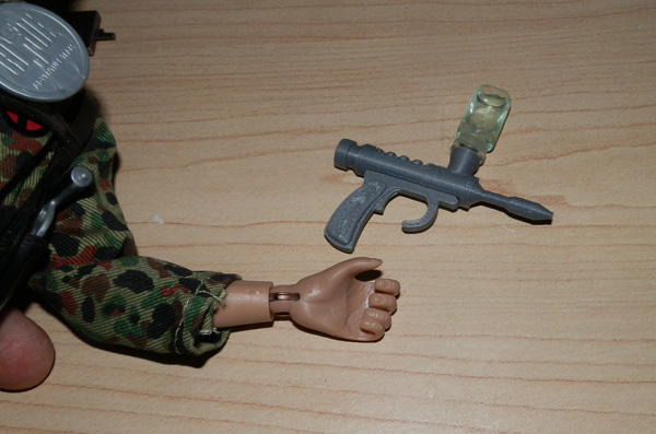
I found this to be just a tad too large. It reminded me of some 1990s 12″ Real American Hero Joe pistols, or modern Action Man guns which tended to be oversized.

So I scaled it down a bit:

OLYMPUS DIGITAL CAMERA

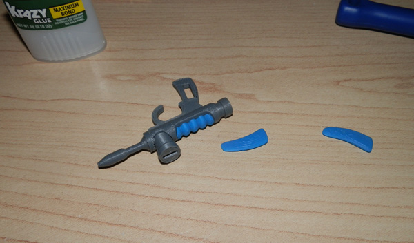
…glued the parts together and attached the bottle:

OLYMPUS DIGITAL CAMERA

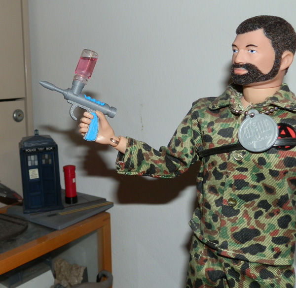
And posed in Joe’s hand it is now actually quite right.
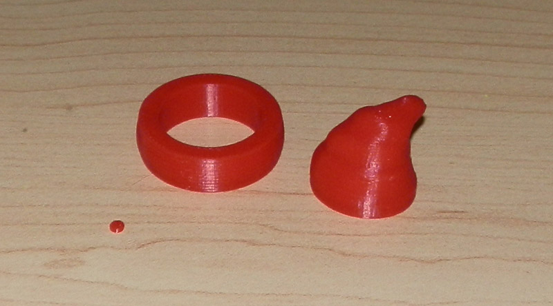
OLYMPUS DIGITAL CAMERA

The Rhino’s Horn

Now that most of the set is together the remaining piece to design and build was the solar-powered prosthetic rhino horn.

I modeled the base in blue, so it can pass as a solar power cell, keeping the electronics going. The middle section is white with eight lenses for a panoramic web-cam that constantly uploads to a satellite through the top section, a GPS locator/satellite uplink just like in any smart phone.

at-rhino-old-horn

at-rhino-new-horn

What’s Next?

So glad you asked.

Some of the GI Joe collectors I know expressed great interest in these sets, so I made available four sets of the bazooka; six darts; an ammo box; and a sealant gun. I sold four in very short order.

Perhaps later I will make more available.

Also, I thought it would be nice to have a case to hold the sealant gun with sealant bottles. I could probably model a briefcase or something, but I have this wonderful aluminum briefcase which is meant for business cards but is a perfect 1:6 Samsonite-like aluminum briefcase for Joe. The sealant gun and vials would fit nicely. But I only had one case.

I made contact with a vendor in China and may be buying a few of them in black, so I can make the sealant gun case. I would use it outright, but would 3D print an insert to hold the gun and vials.


AT Set 3: GI Joe Adventure Team Action Pack Backpack Drone Surveillance

Since my second 3D-printed Adventure Team set, the AT Remote Drone Surveillance,was completed a couple of weeks ago (see the post here and the photo story) I decided that some Joes would want to carry along a Surveillance Drone without having to have the ATV or Trouble Shooter handy.

at-drone-05

Having these mounted on an ATV is fun, and allows me to add an armature carrying a control tablet so Joe can stand next to the ATV and control the whole operation.

Two drones are nice, but sometimes you only need one. And the best way to carry it would be on a backpack. These drones are lightweight but large and cumbersome to carry.

So I designed a portable version of the drone with backpack that had multiple purposes. (Note: There were no changes necessary to the drone itself.)

First, it allows Joe to carry a single drone and control tablet wherever he needs to go on foot.

Second, it removes and acts as a launch pad, with legs to set it on the ground.

Third, it is a solar charging station. The solar cell absorbs the sun’s energy and powers internal batteries that charge the drone when it is attached.

It stores the control tablet for convenient carrying.

I designed this to be very much like an original Action Pack GI Joe set. I printed it in orange and black (mainly) which are traditional Adventure Team colors, and the solar cell is in blue because most solar cells do tend to be blue.

I used 1cm braided elastic for the harness straps, and printed the harness chest piece, the strap clasps and strap adjusters.

Here are the main parts, printed.

at-drone-backpack-main-parts
Seen in this picture is the main backpack frame, the drone carrying and charging cradle, four strap connectors for the frame, four legs, four leg bolts, two strap adjusters, two harness clasps, and the front and back half of the harness connector.

at-drone-backpack-more-parts
Here we have the solar charging cell, the control tablet (seen from the back – the front will have a paper insert) the charging cradle, and the backpack, partially assembled.

at-drone-backpack-main-parts-02
One main thing I wanted, especially after experimenting with a hard printed harness for my GI Joe Adventure Team Action Pack Flight Pack, was an elastic strap, like some older GI Joe sets. I found that 1cm elastic worked well, and I could melt the cut ends to prevent fraying.

My main concern was that I didn’t have to sew anything, so I designed the strap to not have to be sewn at any point.

What I did was, I thought, pretty darned clever. The strap is one continuous length of elastic, melted at both ends. The strap’s middle is sandwiched between the two halves of the chest harness connector with two screws that serve the dual purpose of joining the halves, and anchoring the elastic straps.

Next, the straps go into two black plastic strap clamps on the backpack’s top half. Again, screws hold the parts in place as well as anchor the elastic strap to the backpack.

Then the elastic straps are stretched a bit and clamped again at the bottom half of the backpack with two more clamps, screwed into place.

The clever part here is that now the two straps are used to hold the control tablet in place, which has a seat slotted into the back of the backpack.

Then the straps go through strap adjusters and into the harness clasps. There is enough remnant strap to do a lot of adjustment for body size.

Then the harness clasps have a cylindrical peg that fits into holes on the harness connector, nice and snugly so the strap won’t come out, but not too tight to make removal difficult.


at-drone-backpack-worn
Here’s the Land Adventurer, with backpack on his back.

at-drone-backpack-launching
Here he has placed the backpack on the ground, deployed its legs, removed the control tablet and is ready to launch the drone.

I designed the backpack with a slot in the back to store the control tablet. When not in use, the tablet fits behind the two elastic straps. (Clever me!):

OLYMPUS DIGITAL CAMERA

Here, you see the tablet being removed:

OLYMPUS DIGITAL CAMERA

When the drone is launched, it exposes a solar panel to charge the internal batteries, to keep the drone powered:

OLYMPUS DIGITAL CAMERA

AT Set 2: GI Joe Adventure Team Remote Drone Surveillance

Introducing my second GI Joe Adventure Team set: Remote Drone Surveillance. The set consists of two Remote Surveillance Drones with articulated camera and hide-away landing struts; two launching cradles mountable on an ATV or Trouble Shooter, as well as a rear-mounted Control Tablet on an articulated armature. All designed by me and printed on my Afinia H479 3D printer. Seen here: at-drone-01 at-drone-02 at-drone-03 at-drone-04 at-drone-05 at-drone-06 at-drone-07 at-drone-08 at-drone-09at-drone-10 at-drone-11 at-drone-12 at-drone-13 at-drone-14 at-drone-16 at-drone-17 For the sequel: Retrieve the Lost Space Probe

AT Set 1: GI Joe Adventure Team Action Pack Flight Pack

After some minor visual and a few major internal changes, the GI Joe Adventure Team Action Pack Flight Pack is more or less done. I still want to make some changes, but I’m happy with it for now, and I will be concentrating on a third GI Joe Adventure Team set for a while.

So for now here is the updated Photo Story to introduce the Flight Pack. (I changed some things in the story because it is now a sequel, which you will see shortly.)

Flight Pack designed by me and printed on my Afinia H479 3D printer.

OLYMPUS DIGITAL CAMERA

OLYMPUS DIGITAL CAMERA

OLYMPUS DIGITAL CAMERA

OLYMPUS DIGITAL CAMERA

OLYMPUS DIGITAL CAMERA

OLYMPUS DIGITAL CAMERA

OLYMPUS DIGITAL CAMERA

OLYMPUS DIGITAL CAMERA

OLYMPUS DIGITAL CAMERA

OLYMPUS DIGITAL CAMERA

OLYMPUS DIGITAL CAMERA

OLYMPUS DIGITAL CAMERA

OLYMPUS DIGITAL CAMERA

OLYMPUS DIGITAL CAMERA


I Won!

3DAGOGO.com is a site for people like me to sell (or give away) our 3D designs.

There are other repositories, such as Thingiverse, which have no payment system – it’s all free. Which is nice. But 3DAGOGO offers designs that are guaranteed to print. The designs must include a photo of the printed object.

For the past few months they have had themed design contests.

November was Household objects, with various categories. One was toys. I entered my Airship One:OLYMPUS DIGITAL CAMERA

December’s theme was Christmas and I entered my Afinia Printer Christmas Ornament:
OLYMPUS DIGITAL CAMERA

And they had a grand overall contest, in which I entered several of my designs including my GI Joe Action Pack Jetpack:
atapfp-jetpack-back

Yesterday I got an e-mail from 3DAGOGO.

I won all three contests.

For November I win a t-shirt and a reel of filament.
For December I win a t-shirt and a reel of filament.
For the Grand Prize I win a t-shirt and a Makerbot Digitizer 3D Scanner!!!

This one:

digitizer-main

Am I psyched or what?

The Bot Shoppe Is Open

In August I published my first miniature robot design to Thingiverse. It gets a fair number of downloads. I called it “Tread-Bot” because it’s a simple robot that uses treads to get around.

OLYMPUS DIGITAL CAMERA

The robot was designed to be a board-game piece, but in fact is a tad big for the game I was hoping to use it in. Rather than fitting on a nickel, it does still fit on a quarter; nonetheless, it pushes the design tolerances of my Afinia H479 printer. Some of these parts in test-print had to be increased in size to print right, but they do work.

I liked the design and saw it being part of a cute little line of robots.

Here are the parts of V2.0 of Tread-Bot in its final colors:treadbot-v2-parts

Tread-Bot was supposed to be just the first in a line of these miniature robots that share the themes of a somewhat organically-shaped body and head mixed with less organic, more machine-like parts.

It made sense, since I made the treads tri-tread shaped, that I could re-use the treads in different formats. I figured my second robot of the same theme should use the same treads but upside down.

While the second uses the same treads it is not “Tread-Bot 2”. Rather, I’m going to begin using the robot’s function as a name. This one was designed as a single-armed heavy lifting/carrying machine, and I created him with two strong fingers to grab things.

bot-shoppe-tread-bot-grab-bot

Here are his component parts:
bot-shoppe-grab-bot-parts-2

(I created an alternative three-finger grabber hand too.)

So since this line is only just getting started (I already see several new designs in my head) I needed a name for the line.

The BOT-SHOPPE is born!

One of the people who downloaded the Tread-Bot model on Thingiverse printed one on a Form-1 (drooool!) and here is the result:

robotanddodecahedronx1280_preview_featured

Afinia – Facebook Front Page – My Ornaments

I decided this year to begin a new tradition. Every year I have a 3D printer I will design and print a Christmas Tree ornament using my latest and best printer. Hopefully I will buy new printers as they evolve and become better and much like my first dot-matrix printer, I have had a paper printer of one form or other most of my adult life. This year I decided to use my very first 3D printer, the Afinia H479, and make a Christmas Tree ornament that meant something. So I made a miniature version of the ornament printing a Santa hat ornament.

OLYMPUS DIGITAL CAMERA

A bit meta, as most people who knew about this pointed out. I liked that.

So while this ornament sits proudly on my own tree right now, I also printed one to send to my mother, and also one to send to Afinia, the makers of this printer.

They liked it so much that they wanted to print one for all of their employees, and asked if I would mind sending them the files. I did not mind. So I sent it to them.

(If you want them, you can also get them here. What? You want them for free?)

So Afinia liked it enough that they sent me this image of the ornaments printed in all of the Premium colors they have available:

afinia-ornament-assortment

Apparently they liked it enough to make it their facebook front page image:

afinia-facebook

Afinia also sent me a reel of white premium filament, a printer nozzle and a sheet of their new Build Tac sheeting to print on (which I am loving!)

I’m already thinking about next year’s ornament.


GI Joe Adventure Team Action Pack Flight Pack

I recently made a slight change to the name of my GI Joe Adventure Team Action Pack Jet Pack. It is now the GI Joe Adventure Team Action Pack Flight Pack. I did this on the advice of a fellow collector who said that it didn’t really have the look of a Jet Pack.

atapfp-jetpack-back

However, this design has (fictionally of course) a jet engine in the back pack that forces air out through the engine housings for a forced-air effect that provides upward thrust without jet-flame output that would burn the pilot. But since it doesn’t really look like a Jet Pack, I thought I would take the advice of a fellow collector and call it a Flight Pack.

atapfp-jetpack-top

The otherwise overly long name stands, however, since it means something.

It’s for GI Joe. It’s for the Adventure Team. It is intended to be (retro-actively) a part of the GI Joe Adventure Team Action Pack line, which were generally useful bits of equipment that in some way folded up and were worn on the back for transport when not in use.

This toy that I designed in 2013 has been an important thing for me. I came up with the design, modeled it, with functionality and fit in mind, then I printed it over and over on my Afinia H479 printer until the parts all worked, and even now I’m refining it.

Some news:

Publishing

I published the model on 3DAGOGO. 3DAGOGO is a pay-per-model site and I’ve sold a few pieces there, mostly the Airship I designed.

Afinia

Afinia asked to use this model in their CES booth, which was a thrill to me. I sent them both a yellow and a black (stealth) version along with a GI Joe figure to model one on. It will be on display at CES in their booth. I will post pics if they send me any.

Design Refinement

This is v1.2, which takes most of the design from the first prototype, but adds some things and changes some things to make printing easier and to make assembly easier.

Changes to this version include a more open clip design to clip the under harness arms to the main harness, and a better system to clip the swing-down harness control arms. I straightened them out, because before, if you rotated the joysticks all the way around, the subtle curve in the arm and the joystick bent the arms until they broke. That should not happen now that the arms and joystick cuff are perfectly cylindrical. Also, I made the harness control arms use two pieces so I could screw them to the main harness front, instead of trying to force the pieces together. This often broke the pieces. This version is a tad loose, though, so expect another minor change.

V1.1 had a control screen on those arms, but the screen was too tall. When the control arms were lifted up while the pack was being worn, the screen prevented the arms from going up, becuause it tried to go into the figure’s body. This version flattens it and should work better. I’m still working on that.

Mostly, this is otherwise similar to the other version with some changes to the screw holes to allow easier printing (the first few I made printed fine, but later the printer kept hitching on the screw holes because of their starburst design.)

I also puffed out the cushion a little. The printer doesn’t allow it to print very smoothly, but it’s better, I think, than the original.

Here are all of the parts for V1.2 of the Flight Pack:

atapfp-all-parts

37 printed parts in 3 colors. 4 screws. 2 printed pieces of paper, (glossy paper, on sticky back works, or glue it.)

And here is the assembly process, step-by-step:

atapfp-thumbwheel-engine-mounts
Push one engine shaft into the body shoulder hole, and the other. Place the thumbwheel in the body slot. Rotate the two engine shafts until they fit onto the thumbwheel. Make sure the forks of both engine shafts are aligned (not aligned in the photo.)

atapfp-thumwheel-engine-mounts-snapped
Push the two engine shafts together until they snap onto the thumbwheel.

atapfp-bottom-harness-arms-mounted
Ensure that each harness lower arm is aligned correctly. Place one in the lower bracket (on the body front part) and the other in the upper bracket of the main body piece. This is done so when fitting the two parts together, they can be wiggled into place. This is much harder if you try putting both harness parts in the same body piece.

atapfp-bottom-harnesses-body-joined
Fit the body front and body main parts together, ensuring the harness arms fit into the four brackets nicely.

atapfp-back-saddle-placed
Put the back saddle cushion in place.

atapfp-back-saddle-screwed-down
Use the three longer screws to screw the cushion, body front and body back together. Do not overturn the screws. Once they are tight they should be fine. Further turning will simply weaken the holes.

atapfp-shoulder-harness-placement
Place the main harness into the two holes in the body front piece by gently prying the frame apart.

atapfp-shoulder-harness-pushed-in
Push into the holes until they stop. Test rotation.

atapfp-harness-handles-disassembled
Prepare the harness handle section.

atapfp-harness-handles-assembledPlace the two pieces over the flat front part of the main harness and use the small screw to attach the parts.

atapfp-harness-handles-joystick-one
Push one joystick onto the control arms, rotating as you go.

atapfp-harness-handles-joysticks-both
Attach the second joystick by rotating and pushing.

atapfp-vent-upper-left
Using Krazy Glue, attach the upper right vent by fitting the vent into the aperture.

atapfp-vent-upper-right
Do the same with the upper left vent.

atapfp-vent-lower-right
Glue the lower right vent into the space provided.

atapfp-vent-lower-left
Glue the lower left vent in place.

atapfp-vent-back-right
Glue the lower back right jet vent into the gap. It should snap nicely in place.

atapfp-vent-back-left
Snap and glue the lower back left jet vent in place.

atapfp-control-screen
Glue the control screen into place.

atapfp-at-logo
Glue the Adventure Team logo in place.

atapfp-engine-housing-vents-disassembled
Prepare the engine housing and the three vents.

atapfp-engine-housing-vents-assembled
Glue them in place.

atapfp-engine-brace-first
This part is particularly hard. Coordinating three of these is a difficult feat of manual dexterity. So we glue the first engine brace in place so the flat part is towards the top (the uppar part has the ring aperture inside to let jet air flow over the body.) The curved part points downward.

atapfp-engine-brace-second-hub
Then glue the second bracer in place and glue the hub onto the two braces being very careful that the square hole in the hub is flat with the engine housing arm grip (the round part that connects the engine housing to the body.)

atapfp-engine-brace-third-vane
The next operation is the most difficult. Placing a bit of glue into the third gap in both the engine housing and the hub, push the bracer into place. This can be quite difficult. When it fits together, the three bracers hold the hub in place by sheer pressure, but we glue it because pressure can break the connection. Then glue the engine vane into the center of the gap.

atapfp-engines-on-side
For traveling on the back of the pilot, and for transporting via ATV, push both engine hubs into the engine mount shafts.


2013 Christmas Ornament – 3D Printed

Someone gave me a great idea – model and 3D print an ornament for the Christmas Tree.

I thought this was an absolutely great idea. Since Christmas Tree ornaments are an important part of our family tradition, I thought I would make one this year, the first year I got my 3D printer, and every year after, to show the evolution of both my ability, and, I hope, the technology.

So for the first one, the subject matter seemed obvious!

The Afinia H 479 printer which had just finished printing a Santa hat!

So I started sketching, and then began modeling. Here is the 3D model:

OLYMPUS DIGITAL CAMERA

(Sorry. The photo is taken using a camera off my monitor because my PrntScrn button just chose this moment to stop working. I will require a reboot and I’m busy right now.)

The one issue I couldn’t really solve was the color of the printer. The real deal is kind of like primer, but glossy. It’s a maroon color. I have no filament that even comes close, so I chose orange to be a bright, happy color. I could also have used green, which would also hammer home the Christmas theme, but it seemed a bit much. Still, I may go with green.

Anyway, to test, I printed a prototype which, as usual, outlined several issues to fix.

You can see here some of the issues, but there are others you can’t see as easily. Note the separated sections of the text: “2013”. I have to thicken the thin lines because the printer has a minimum size tolerance for area.

OLYMPUS DIGITAL CAMERA

Also easily seen here is the broken spool holder. The shaft is too thin.

After fixing those issues and re-printing some parts, here is the first assembled (day-glo yellow) prototype:

OLYMPUS DIGITAL CAMERA

There is a hole for a screw eye, which may be too small, but that’s easily fixed too.

Note: One reason to print test prints is to make sure everything fits. It’s only theoretical in the model, you have to print it to see. This pointed out several issues, and one was the height. The printer is too short in this test print. Fixing it for the real print.

Here are the black parts:

OLYMPUS DIGITAL CAMERA

  • Two spool halves
  • The Initialize switch
  • The print bed
  • The print bed heater
  • The print head fan

Here are the white parts:

OLYMPUS DIGITAL CAMERA

  • Spool Holder
  • Hat Fringe
  • Print Head
  • Hat Tassle
  • 2013 Year

And the red parts:

OLYMPUS DIGITAL CAMERA

  • Red LED (in case I want it. I am also printing a green one. The LED flashes red and green on the printer.)
  • Reel of red filament
  • Santa hat

And the final parts, in day-glo yellow and silver:
OLYMPUS DIGITAL CAMERA

  • Warning labels
  • Z-Axis Motor
  • Nozzles

And here’s the finished product!

OLYMPUS DIGITAL CAMERA