Dinky Scaled Freighter/Pallet Pod Containers

In Space 1999’s first episode “Breakaway” we see Eagles transporting nuclear waste containers in freighter or winch pods for storage on the dark side of the moon. When the nuclear material begins to become unstable, winch pods are used to distribute them to alleviate the approaching critical mass.

eagle-unloading

Here are a few of the real Nuclear Waste Canisters as seen in the episode:
eagle-nuclear-waste-canister

Here is someone’s (sorry, I forget who. If you know, I would like to attribute it to the proper person) custom-made Freighter/Pallet pod made from parts of the Product Enterprise Eagle, to fit those models:
eagle-freighter-pallet-pod-real

A couple of months back I spent some time modeling a Winch Pod and a Freighter/Pallet Pod for my 4″ Konami Eagles and also for my 10″ Dinky Eagles.

One thing I modeled was the nuclear waste container. It was a single piece, a fairly simple 3D printed cylinder, with rings and a cap. I would paint the rings and create my own water-slide decals to give them the warning label the canisters had.

dinky-freighter-canisters-plain-painted-01

You can see I found painting the black rings to be quite difficult. Getting anything consistent or even was near impossible for me. I’m not that skilled at painting models.

So I decided – hey, I have a 3D printer after all, I don’t have to print these as a single piece. In fact I can print them in two colors in their individual rings.

So I set out to break the simple model down into a base with a post (that also forms the center of the cap at the top) with two black rings, a central body section, and a cap.

dinky-freighter-canisters-all-pieces

Here, the first black ring is slipped on over the base post/cap:
dinky-freighter-canisters-bottom-ring

Then the central body ring slides on:
dinky-freighter-canisters-body

Flanked by the top black ring:
dinky-freighter-canisters-top-ring

Topped off with a white cap that snaps to the central hub:
dinky-freighter-canisters-cap

I used clamps to hold them while the Super Glue was drying. Then I applied water-slide decals I designed and printed myself.

Here you see the painted version on the left and the printed version on the right: (I think I can probably thin out the rings a bit…)
dinky-freighter-canisters-painted-vs-printed-02

And here is what the finished Dinky Pallet/Freighter Pod looks like:

dinky-freighter-canisters-loaded

NOTE: For anyone who buys these models from me at my shop (Fourth D) on Shapeways, you may want to print the decal sheet I created. The two links below are to PDF files you can print.

Pod-Decals-Better-Layout

Pod-Decals-Instructions

You can print them on white waterslide paper either in laser or inkjet (make sure you have the right paper and follow instructions that come with the paper) or you can print them on simple white paper and use simple glue if you like. The decal sheet has both the Konami and Dinky scaled decals. Also, the instructions for the decals (for waterslide) are available here.


1:64 Scale Deckard’s Car Custom

I posted already about preparing my ERTL Blade Runner Deckard’s Car car for a custom version.

ertl-deckard-car-side

This is what the car looks like out of the box (or card). These are fairly rare these days and sell for about $25.00 and up, depending on condition.

Now you know Deckard didn’t have a big honkin’ “Blade Runner” logo on the back of his car, nor was it metallic brown.

Here is the box cover of the recent Fujimi model kit of the car in 1:25 scale. (I have this kit and will probably do something with it this winter.)

fujimi-deckards-car-1

Here is a restored or replicated version:
br-deckard-car-for-real-01

So here it is, finished.

Beside the original ERTL car:
my-br-deckard-car-with-original-01

I used some of the decals from the Fujimi sheet, scaled down:
deckard-decal-sheet

Details:

  • I painted the car a slightly rusty orange.
  • I painted the door bumpers black.
  • I cut out the thick vertical window posts.
  • I printed front orange curved lights over the bumpers. Due to the shape, I had to chisel out some space in the inside bumper
  • I painted the interior tan and black.
  • I put decals on the dashboard.
  • I painted silver detailing.
  • I printed custom headlight decals.
  • I printed custom decals for the 56 on the front bumper and the rear side.
  • I printed custom POLICE decals for the angled front sides.
  • I printed a decal for the top circle.
  • I painted tail lights.
  • I cut a small bit of glossy cardboard from a product package, scored it and painted it silver for the windshield guard.

my-br-deckard-car-left-01 my-br-deckard-car-rear-01 my-br-deckard-car-right-01 my-br-deckard-car-front-01

This is, supposedly, a shot of the real car taken some years back:
deckard-winfieldshop4


Adventure Team Backpack Surveillance Drone – Now in AT Colours

Last year I posted an article about my 3D printed Adventure Team set, the Action Pack Backpack Drone Surveillance. I designed it and 3D printed it on my Afinia H479 printer. Originally the drone was white with black structure and red highlights. The backpack was orange and black. These are acceptable Adventure Team colors.

at-drone-backpack-launch-base

But I decided I wanted to see how it looked in the more typical Adventure Team colors of red and yellow. I bought some Afinia Premium Red filament for the first time. (I had some Afinia Premium Yellow before, and I printed my Backpack Jetpack with that material.)

The result is pretty nice:

at-drone-backpack-with-drone-complete-01

Note: To apply my laser-printed water-slide decals I had to do some experimentation. These decals do not stick to ABS plastic. I discovered that spray-painting the top part with a satin clear coat paint, the decals would stick pretty well. Another spray coat over it and it should seal them down nicely. (Of course rough treatment may still make them come off.)

The Parts and Assembly

You saw how the drone was assembled (though in a slightly smaller scale it is an identical process) in my post about the Cotswold Deluxe Midnite Mission set.

The backpack frame, legs and screws:
at-drone-backpack-parts-01

The legs form the side of the backpack when being carried, and support the frame as a launch platform for the drone when in use:
at-drone-backpack-legs-assembled-01

Next, the harness. It is comprised of a 22-inch strip of .375 inch wide black elastic. First, I fold the elastic in the middle and place it into the space modeled into the harness bracket front half. While this picture does not show it, the red half has a channel modeled to fit the elastic on a folded angle.

at-drone-backpack-harness-parts-01

Then the two short, stubby screws are screwed into the black back plate through the elastics to hold it firmly:
at-drone-backpack-harness-screws-01

Here are the four black strap brackets that will hold the elastic harness in place on the frame:
at-drone-backpack-harness-brackets-01

The elastic is carefully placed so there is a 7cm distance between the top bracer and the harness chest piece. A screw holds the elastic and the bracer in place firmly. Then the elastic is stretched somewhat (consistently) to the lower bracer and that is screwed onto the frame. There is equal tension between the two bracers for a purpose:
at-drone-backpack-harness-attached-01

Next the strap adjuster and harness clips are placed onto the elastic strips:
at-drone-backpack-strap-adjusters-01

The completed harness:
at-drone-backpack-harness-complete-01

Next, the solar cell (which charges the drone’s recharging batteries when it is in the air) is glued to the circular aperture:
at-drone-backpack-solar-cell-01

On top of this the drone’s holding tray is glued: The drone fits perfectly between the three clips, and the top clip is used to free it by pressing gently until the drone is released from the grip of the tray.
at-drone-backpack-drone-tray-01

Here you see the touch-screen tablet used to fly the drone, and to monitor the drone’s camera capturing ability. This is a single printed piece with clear-coat and a glossy printed screen spray-glued (with permanent glue hopefully) to the surface:
at-drone-backpack-control-tablet-01

Ok, I’m going to claim some cleverness now. This tablet stores perfectly flat in the backpack frame in a cavity modeled to fit it, held in place by the harness straps:
at-drone-backpack-tablet-storage-01

Here it is, stored fully:
at-drone-backpack-tablet-stored-01

Lastly, for the backpack, these four black “bolts” are glued onto the legs (so as not to interfere with the screws) to finish off the look:
at-drone-backpack-leg-bolts-02

Et voila:
at-drone-backpack-with-drone-complete-01

Cotswold Collectibles – Deluxe Midnite Mission Set

cots-cover-image-midnight-mission

At the GI Joe Convention in Dallas in April I met Greg Brown of Cotswold Collectibles. I had sent him some of my 3D print samples some months earlier and he expressed interest in doing some project work together for Cotswold Collectibles, which had recently begun to issue mail-out catalogs in full color again, featuring some Adventure Team-themed outfits and full sets

He showed me plans he had for a complete stealth set which harkens back to the good old days of the GI Joe Adventure Team. Here was a modern take on the Spy Island set, and it included a black and silver version of my AT Surveillance Drone which I had designed last year and 3D printed. The drone featured in one of my diorama entries at the Convention, seen here:

IMG_1174

The drone, printed in white, hovers above the scene, suspended by a thread on an armature.

I began work immediately. First, the construction of my drone was a bit flimsy, especially the working camera head which pivots around a hub using a tenuous connector that was easily broken and came loose easily. I opted to fix that by using a screw. Second, the struts that hold the central hub to the outer ring were individually printed and had to be glued together in another relatively tenuous connection.at-surveillance-prototype-3

My first improvement was to combine the three struts with the central hub for a single, strong part. Then I created notches in the ring and pins in the struts so the hub part could snap to the body accurately and strongly. The rest remained relatively unchanged; the legs (not seen in this photo) which form the bottom segments of each strut hinge down as landing gear.

But the drone had to fit into an existing Cotswold backpack which Greg sent me. I found that I had to scale the drone down to 75% of the original. This meant that moving parts may not work, since tolerances at that scale would be different.

cots-drone-scaling-test-01

(I test print in neon yellow to make sure I don’t confuse them with final parts. And I have a lot of neon yellow with not much use for it.)

To my surprise, I printed three test drones. One at 50%, one at 66.66% and one at 75% of the original size. To my utter shock and astonishment, each one functioned perfectly when printed. Even the 50% scaled version had working legs that folded without an issue.

The 75% version fit the backpack perfectly.

cots-drone-fitting-backpack-01

I began printing a couple of test models, sent them to Greg for approval, then began printing in earnest.

Here, I assemble the drones:

The bodies are split into an upper half and a lower half. The lower half has spaces for the legs to hinge down.
cots-drone-leg-assembly-01

Small pegs align the upper and lower halves. The legs are held in by square blocks that, when pushed into place, form a perfect hinge space.cots-drone-leg-assembly-02

The pegs are put in place, and the top glued to the bottom, clamped down by six strong clamps.cots-drone-body-clamping-01

Next the hub gets snapped in place and glued.
cots-drone-hub-assembly-01

Then a small screw is used to screw the camera head to the hub.cots-drone-camera-assembly-01

Then (not shown here) the camera is placed in the camera head by friction so it can swivel on its axis freely.

Then the repulsors are glued in place and a jet vane is glued to the top of the hub.
cots-drone-complete-01

And after a heck of a lot of work, I had 30 ready to go:
cots-drone-all-done-01

Then I had to design the arm controllers. I had a simple idea in mind and wanted it to be a single piece. But the design made me want an accent color so I made the control pad red on a silver cuff that can snap to a GI Joe’s dressed arm.

cots-drone-controllers-all-done-01

The space below the control pad in red is reserved for a sticker which will show the view as seen from the drone’s camera.

So here are some pictures Greg posted featuring the finished prototype:

cots-midnight-mission-set-01 cots-midnight-mission-outfit-05 cots-midnight-mission-outfit-04 cots-midnight-mission-outfit-03 cots-midnight-mission-gear-01

And here is the catalog, which I got in the mail a couple of weeks back:

cots-catalog

P.S. I am currently at work on my second Cotswold set. News on that as I am allowed to post it. Stay tuned.


Designing and Printing with the Afinia H479 – Essential Tools

The Afinia H479 comes equipped with a good set of basic tools:

afinia-equipment-800

1 – A reel of Premium White filament.
2, 3, 4 – Power supply, power cord, USB cable (I list these together because they are essential parts of the printer, not extra tools)
5 – 3 perf-boards – these are what you clip to the print bed to print on
6 – 6 clips – these clip the perf-board to the print bed
7 – Filament tube – (this doesn’t scan well in the photo) It is a channel for the filament to go through when extruding. It helps keep the filament on a good angle while printing
8 – Spool holder (also doesn’t show well in the photo) This is good only for Afinia Premium reels. (More on this later)
9 – Nozzle wrench – this is for removing the extruder nozzle if it becomes clogged or needs a cleaning
10 – Set of three Allen Keys – for removing the various bolts used on the Afinia
11 – Set of replacement screws in case any go missing
12 – Heat-resistant gloves – 3D printing is a hot process, so using gloves can save you a lot of hand heat
13 – Putty knife – this is for removing the print from the perf-board, and for cleanup
14 – X-Acto knife and blades – for cleanup
15 – Wire cutters – also for cleanup
16 – Tweezers – also for cleanup

Most of these are the very basic tools needed if you wish to do 3D printing.

However, if you plan to do a lot of 3D printing (like me) there are other things you will want to have. None of these are necessary for basic printing, but believe me, you will want to have these if you are serious about 3D printing and doing it right:

When I bought my Afinia H479 it was part of a bundle purchased through a third party, an approved vendor of Afinia. It came with the printer (and all you see above) bundled with three reels of Octave filament in my choice of colors, a set of 5 small chisels, and an extruder nozzle temperature switch. I found these to be absolutely necessary for any serious printing.

Set of Wood Chisels

tool kit A

The X-Acto knives that come with the Afinia are great for cutting. But most of cleanup is not cutting the plastic, it’s prying and wedging along natural separation lines. I would recommend not using the X-Acto knife at all. I’m more likely to expect the blade to snap than it to work well.

You can purchase a set at a hobby or wood-working shop. The Octave 3D Printer Tool Kit A (shown) is what I bought with my Afinia as part of the bundle. It is a set of five hardened steel wood chisels and they are essential for cleanup. This one comes with a flat blade, an angled blade, a 90 degree wedged blade, and two curved blades.

With these, cleanup is much easier.

Octave Extruder Nozzle Temperature Switch

octave-extruder-nozzle-switch

Afinia’s Premium Filmanet works perfectly with the stock Afinia H479 printer. This filament extrudes at around 260° Celcius. No problems. Cleanup is easy, it prints beautifully.

However, most ABS filament prints at a lower temperature. You can use third-party filaments on the Afinia without changing the extrusion temperature, but the plastic fuses harder, making removal from the raft layers and cleanup far harder. Printing at the correct temperature for the filament makes cleanup so much easier!

The Octave Extruder Nozzle Temperature Switch is a simple device. It is a two-way switch with a resistor on the active circuit. It is attached to two plugs. The extruder nozzle is attached to the Afinia by identical versions of these plugs. You simply separate the plugs on the Afinia, and fit this directly in-line. All you’re doing is inserting this switch into the circuit.

It also comes with a plastic printed part to secure the switch to the top of the Afinia Extruder Heat Shield.

If left in the off position, the Afinia prints at its native temperature of 260°C. If you turn the switch on, restart and re-initialize the printer, it now prints at around 230°C.

Octave no longer sells this simple switch on their web-site. They have replaced it with two more sophisticated switches. One has 8 different temperature settings, and the other can do 127 settings, each one using similar 8-bank DIP switches.

multi-setting-Temp-switch-w

Warning! – This add-on hardware is NOT approved by Afinia and sending a printer to them for repair under warranty with the switch attached may void your warranty!

Octave Adapter and Filament Reel Holder Spindles

filament-reel-holders

Octave makes available free on its web-site a set of .STL files to print a modular filament reel holder system. Download these and get printing.

The reel holder that is supplied with the Afinia H479 is not useful for many third-party reels which have different size holes and different widths. Also, it is screwed to the body of the printer so fast swapping for a different holder is difficult.

Octave’s Adapater is a housing that screws to the Afinia and then any number of different reel holder spindles can be swapped in and out in seconds.

They supply various reels that fit the housing, but I found that several of them could be combined into one singular design, so I made some modifications and made available my own multi-reel holder.

huxter-universal-reel-holder

It works by having several consecutive dips in a rod spaced for the various known reel widths, and is small enough around to fit most reels. The Afina reel with its large hole does not need a large curved holder. It works perfectly fine on my “universal” reel spindle.

This works with almost all reels I have printed with including Afinia Premium, Afinia Value Line (with a thinner spool hole) and Octave’s wider spools. It is downloadable free from Thingiverse and fits Octave’s universal adapter.

Borosilicate Glass

borosilicate-glass-sheet

The perf-boards that come with the Afinia are fine for most normal printing but they have serious drawbacks for serious printing hobbyists. ABS is extruded into the holes during printing of the raft layers and it grips the print to the bed fairly well. It can also be covered in blue masking tape which holds very well for smaller prints. However, you will begin to notice that on objects with a larger base, corners and edges will peel up during printing no matter what you do, as long as you use these perf-boards. Warping will be a constant issue.

Now it is not.

I was skeptical at first, when the guys at Afinia talked to me about their new Borosilicate glass. But I was eager to try it so I bought three sheets.

First, it is thicker than the perf-boards, and requires larger clips to hold it down. You will have to recalibrate your nozzle print height since, as I said, thicker.

Printing on the glass alone does nothing useful. The real trick to this method is the acetone slurry you will have to mix.

Luckily, this is fairly easy and the glass comes with instructions. Simply put, you mix acetone with 10% (by weight) of scraps of ABS. You can use rafting cast-off, or clip small lengths of unused filament right off the reel. (Use the scrap.) Cut it up into small bits and put it in a sealed glass jar with the acetone and stir for a while. Let it sit for a few hours and soon you will have a thin soupy mixture of acetone and ABS called slurry.

Get a vinyl brush (not plastic – acetone melts certain plastics) and use it to brush a thin layer of the liquid slurry over the top of the Borosilicate glass and let it dry. It dries in seconds.

Then clip the Borosilicate glass to the print bed with the (supplied) larger clips and print.

Amazingly, the raft layer bonds to the slurry on the glass like crazy! I have no idea whay sorcery is involved but it works! And removal? Believe it or not when the glass cools, (two-three minutes) the print peels up better than the perf-board. As it cools you can hear cracking sounds. This is the ABS unsticking itself from the formerly hot surface. It lifts off as if it was never stuck in the first place.

This is magic you simply have to see for yourself to believe.

I have been using this method exclusively since I got it and I have had almost no warping or peeling-up of a print (except where my slurry was incorrectly mixed.)

Calipers

VernierCaliper

If you are into designing 3D models for printing like I am, not just downloading and printing things, one of the most essential tools you will need is a measuring caliper. This is a device with a ruler on a sliding arm with claw tips that can be used to measure distances of widths of objects. Perfect for measuring a pipe’s diameter, or the inside diameter of a hole you need to make a plug for, it allows you to accurately measure distances which you can than use in designing your 3D models.

digital-caliper

You can also buy digital versions but for my purposes, I figured a standard one would suffice so I got one much like the one pictured. I like it, but the digital versions are calling me… I must get one, but they are much more expensive.


Summary

I have been printing with an Afinia H479 for 14 months. I have printed literally thousands of individual parts, hundreds of print runs, completely used up a dozen filament reels, currently have more than a dozen active reels, and I have a fair amount of expertise in printing with the Afinia H479 printer. I still say that along with my Commodore 64 in the 1980s, this is the best machine I have ever purchased. I have been waiting for this machine all of my life, and I now have it. You can count on me for advice on making your printing life better.

Tricked Out Afinia Printer

afinia-tricked-out-detail

Some time ago my 3D printer (Afinia H479) had an issue with a broken internal part. The part was, itself, printed by an Afinia printer. The folks at Afinia “fixed my printer by e-mail”, sending me a file to print a replacement part, and then sending me a physical one by courier as well, in case my printer was incapable of printing the replacement.

OLYMPUS DIGITAL CAMERA

I super-glued the broken part together which held well enough for me to print a replacement, which I put into the printer.

Perhaps not surprisingly, there are around a dozen or so parts in the Afinia that were printed on the Afinia, many of which are internal and hold the drive belts and other stuff.

But when my fan hood was causing me some issues with the new, larger clips used for the Borosilicate glass I bought, I mentioned it to the guys at Afinia and they sent me the file, and I made some adjustments, and printed the new fan hood – in blue! (Note: I already had the file in .UP3 format, which means I could print it, but I could not edit it. They kindly sent me the .STL version so I could make the necessary changes.)

It got me thinking. The Afinia software installer comes with all of the parts you may ever need to print, so I thought, now that I have so many colors, why not print one of each in as many colors as I can?

Here is the result.

afinia-tricked-out-01

You see here a stock Afinia H479 printer, but with some add-ons I have been using for a while.

  • The protective heat shield I printed in Afinia Premium Yellow.\
  • The fan hood I printed in Afinia Premium Blue
  • The A_O on the hood is a piece which holds an Octave temperature switch which I now use to switch between ABS filaments intended for the Afinia, and other filaments which print at a slightly lower temperature. I printed this in Afinia Premium Red.
  • At the upper left is the modular spool system Octave created, and I updated. The Spool Nipple Base is printed in Orange-Red.
  • The Spool Nipple is printed in Zen Toolworks Silver.
  • The Spool Housing (lower left) is printed in Octave Green. This holds quickly replaceable spool holders.
  • The orange spool holder (holding a reel of Afinia Premium White) is printed in Octave Orange. I modeled this myself to hold several different reel designs without having to swap out holders. It uses increasingly deep gravity dips in order to fit at least 3 different reel sizes.
  • The neon yellow spool holder on the table is designed specifically for a small 1Kg reel (I have only one, the red-orange)
  • The print bed is loaded with a sheet of Afinia Borosilicate Glass which has made my printing life so much easier! It is clipped with four red clips.
  • On the print bed is a trophy my friend and I designed and printed for an internal company competition.
  • I did not replace the main head unit which holds the motor, feeder and nozzle machinery. It remains white.

I apologize that the lighting isn’t great. Detail gets lost. I will try for a better shot later. Particularly the two yellows look almost the same, and they are NOT the same, not the least bit.

Thunderbird 3 – Original Version

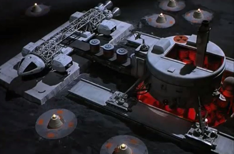
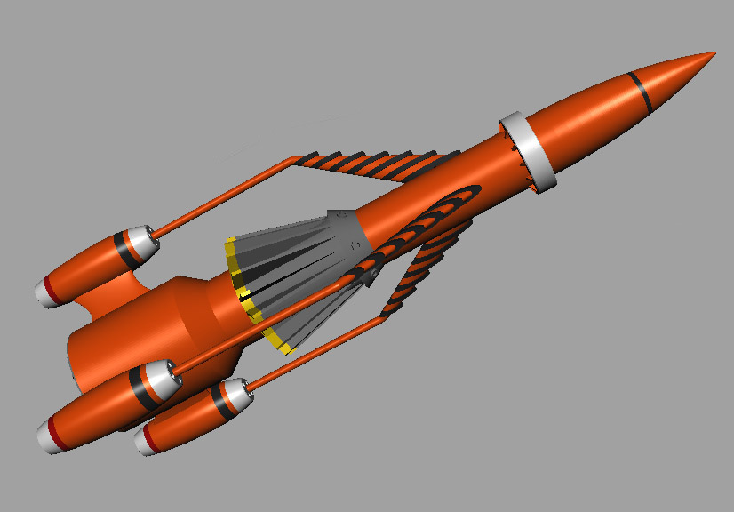
This is the original Thunderbird 3, space rocket from the TV show Thunderbirds. I modeled it almost 18 years ago in Lightwave. I found the files, had them converted to Maya and I refined the model quite a bit, including all separate pieces per each color, and reinforcing slots, tabs, and even channels for coat-hanger wires for strength down the arms.thunderbird-3-model-near-complete-01

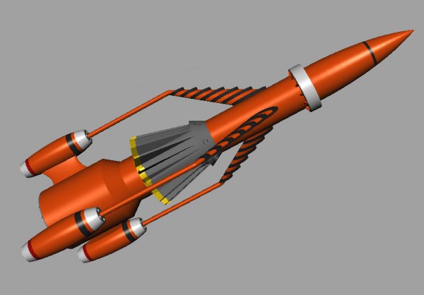
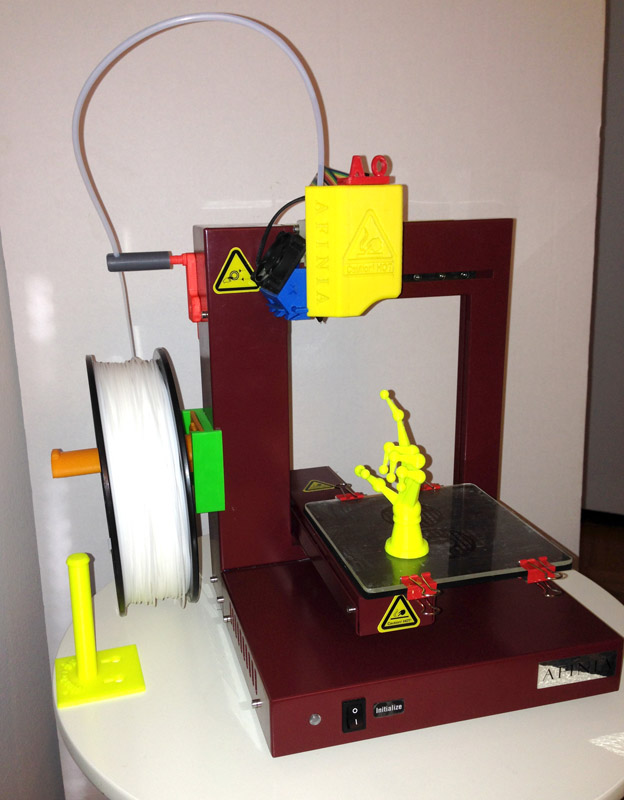
Last year, one of the first things I was excited to do with my Afinia H479 printer (which has dropped in price, by the way, so check it out!) was to print a large model of the re-visioning of Thunderbird 3 that I had designed in Lightwave about 15 years earlier.

tb3-v1-built-up

Back then, before modeling this variation, I also modeled the original Thunderbird 3.

I still have those old Lightwave files, so I had a friend at work convert it to an .FBX file so I could import it into Maya and pick up where I left off. I decided to update the model for printing. And while I am currently working on a secret commission (which I will certainly talk about when I can – nothing huge, but very interesting) I took a bit of time to test-print some parts.

The original model was made for rendering, so it wasn’t overly smooth around. It had something like 24 vertical cuts on all cylindrical shapes. So I vastly increased that so I would get a nice, smooth print, and proceeded to redesign the whole thing from scratch using the basic shape of the original old model.

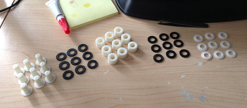
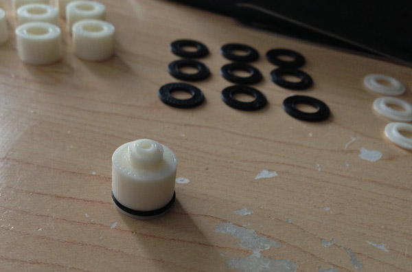
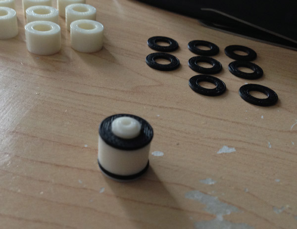
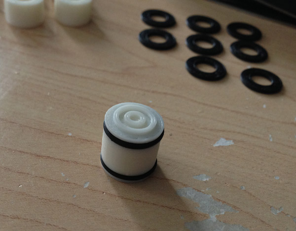
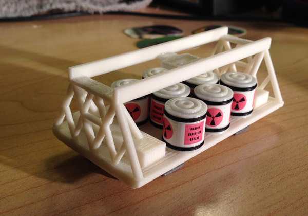
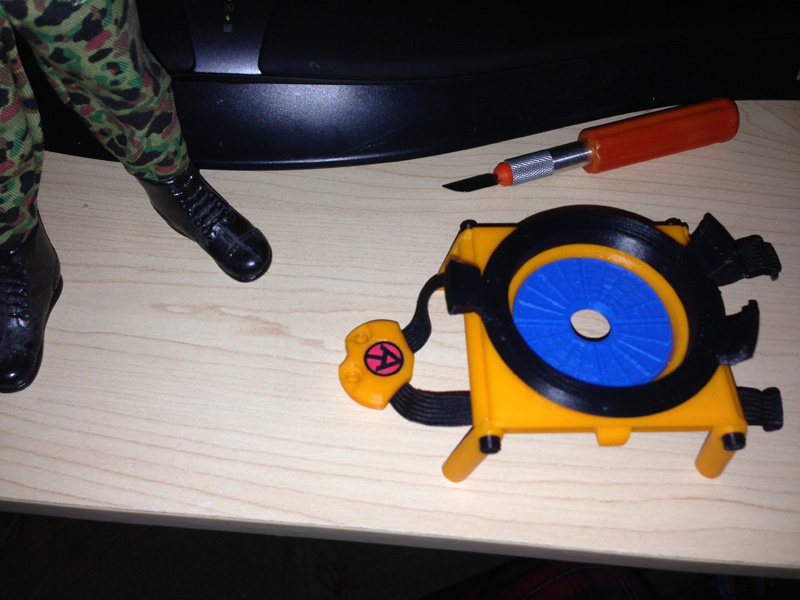
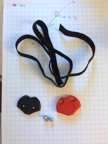
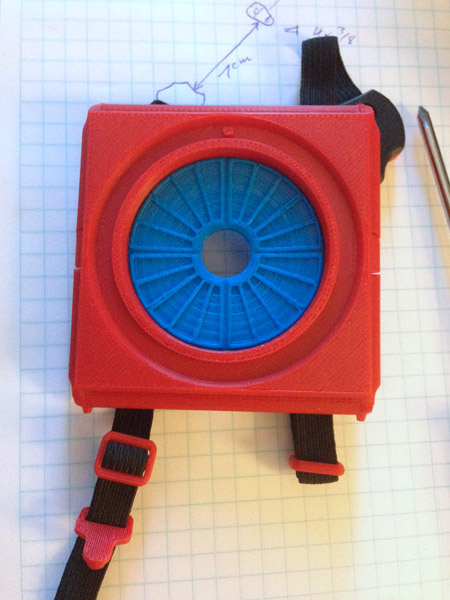
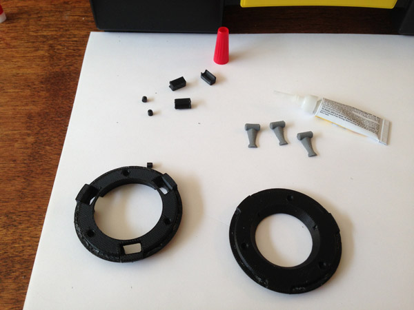
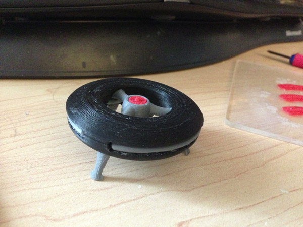
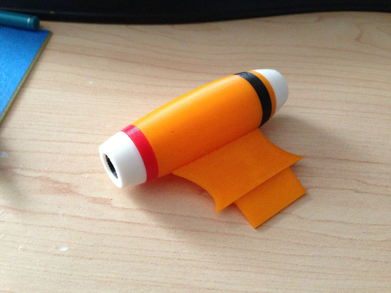
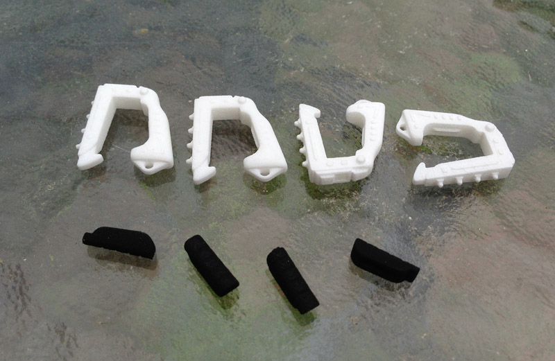
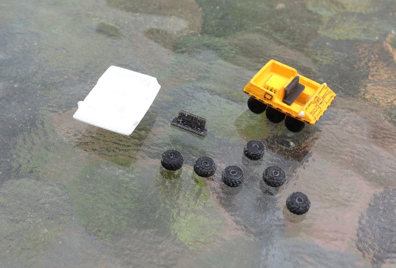
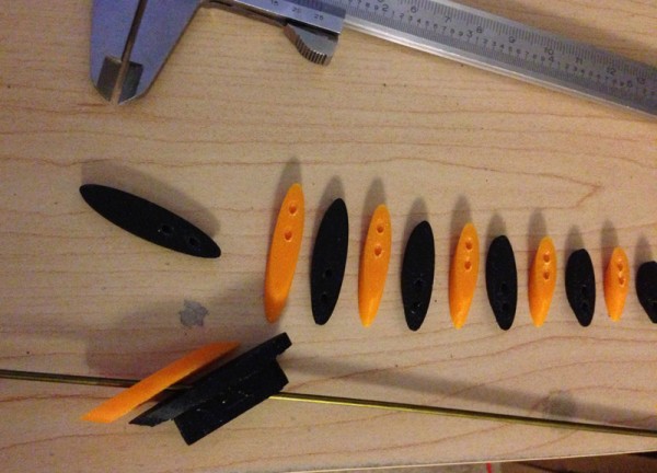
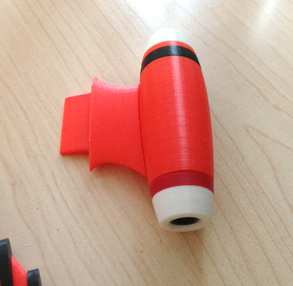
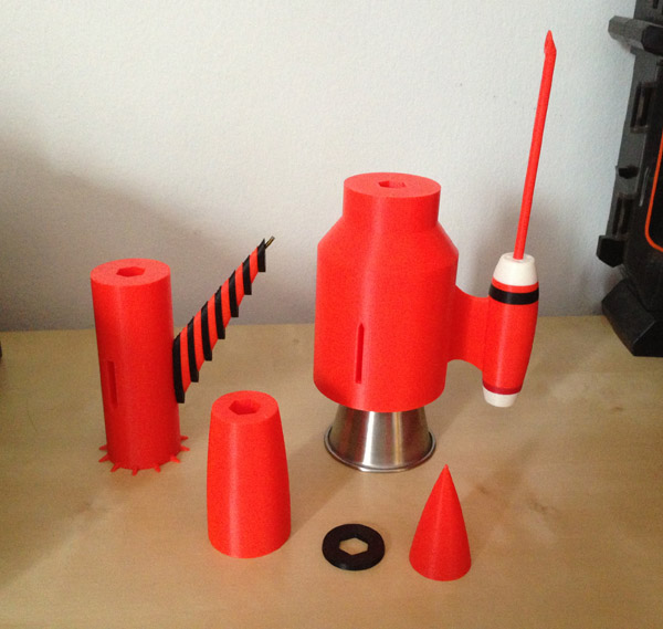
Here are all the pieces that make up one of the main engines:

tb3-original-engine-parts-test-print-01 tb3-original-engine-parts-test-print-02

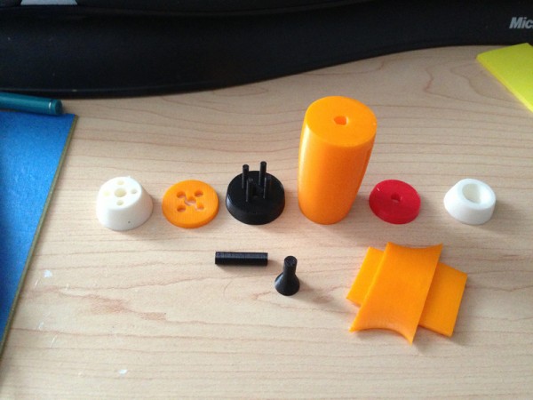
I tried this orange, but it’s way too neon orange. And I tried red, but it really isn’t supposed to be red either. In fact, that one red stripe at the bottom of the engine is supposed to be red, and visible against the darker orange that TB3 should be.

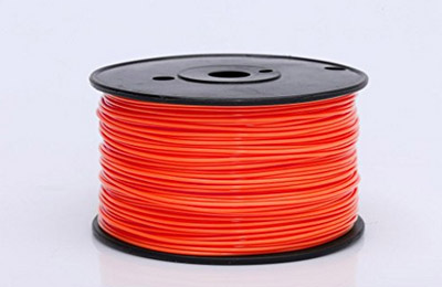
So I ordered a red-orange filament, and when it comes in I will reprint the orange pieces you see here and post new pics. Hopefully that filament will do the job. I’d rather make this of native colors than paint it, but if I have to paint it to get the right tone, I will.

Update: July 7, 2014 (wee hours)

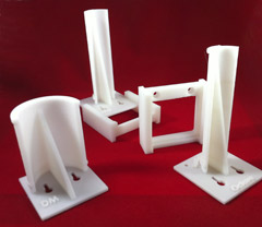
I spent Independence Day weekend completely re-arranging the home office space. I didn’t have much time to model, but I did remodel the upper engine arms to make the pips more accurately spaced. I split the arm out into individual parts, then modeled a wire rod and cut holes in the arm pieces.

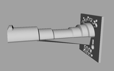
This is a color view from my modeler showing the completed model:

thunderbird-3-model-near-complete-01

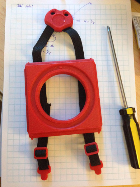
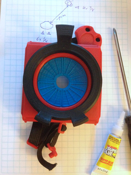
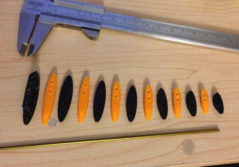
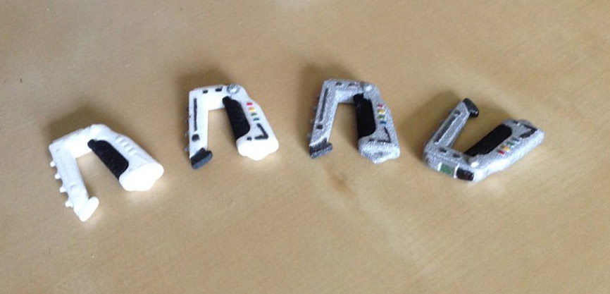
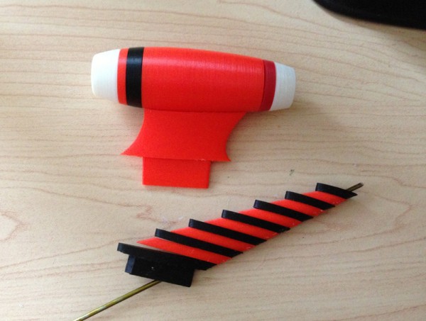
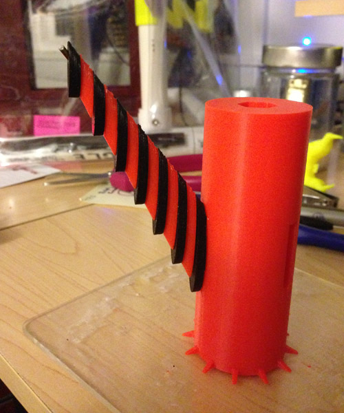
Here are the arm pieces (with the exception of the bottom piece which bends into the vertical rod.)

upper-arm-pieces

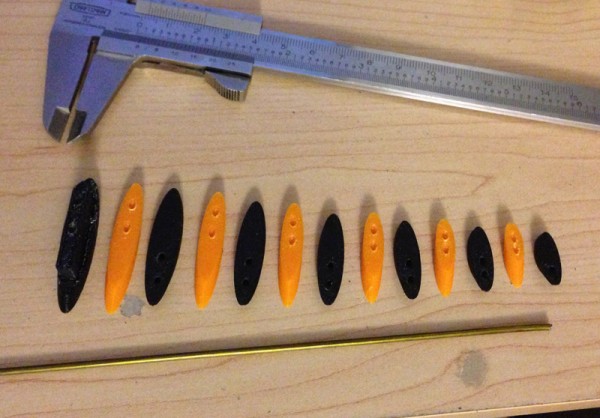
The rod is a segment of a wire coat hanger. I drilled two holes in each piece which should force very accurate alignment and a lot of reinforcement for strength when the model is done. (Note again: This orange is not the final color.)

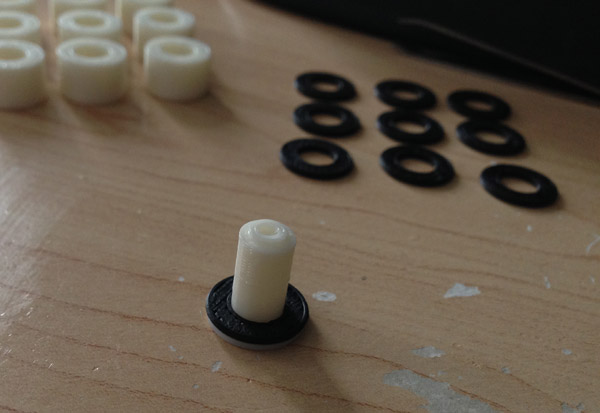
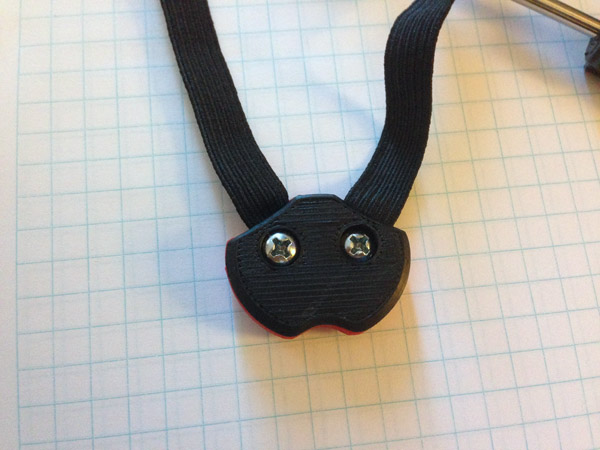
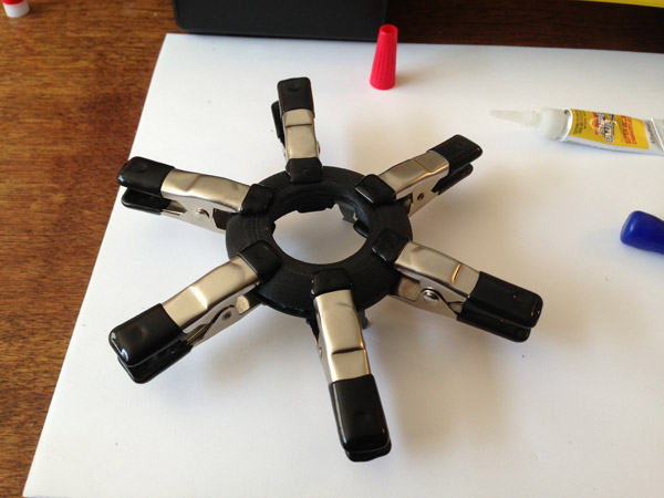
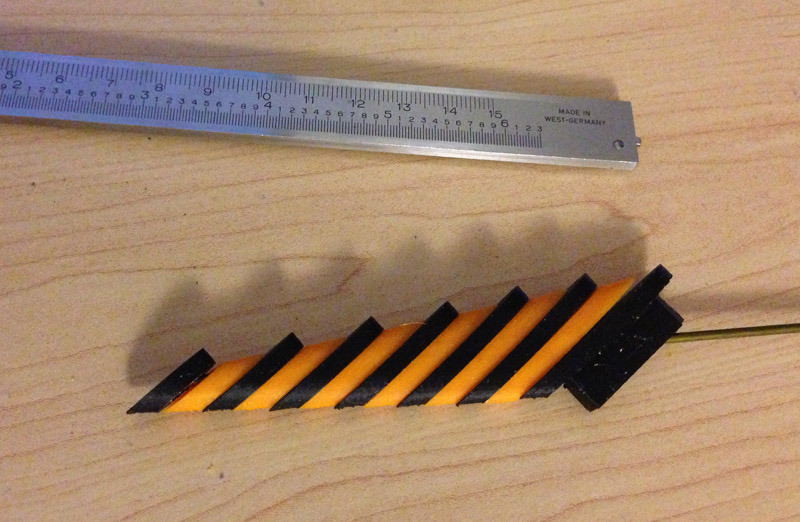
Here you can see how the first two pieces are fitted onto the rod:

upper-arm-pieces-wire

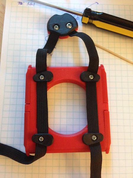
Then the rest, squeezed together, form a solid arm:

upper-arm-test-assembly

I’m really curious to see how my red-orange filament I ordered turns out. And what the final model will look like.

The next updates here will be showing the model printing in progress, since the computer modeling is now finished.

Update – July 8 – New Filament Has Arrived

orangered-filament

I got the new filament in the mail yesterday. When I opened it I was a bit disappointed. The color was called “orangered” on the website, and of course web photos can’t be trusted. But to me it seemed way too red, and not as orange as I would have liked. I put it up against my normal red reel and I didn’t see much difference.

Also, a bit of a snag – this is a one pound reel, which is non-standard. Usually reels come in 2 pound reels, and the reels are bigger. Afinia Premium comes as 1.75 pounds on a thinner, but larger reel.

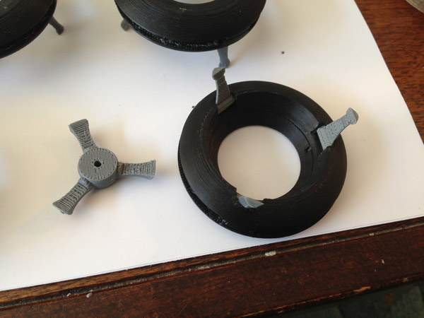
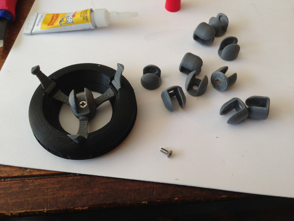
But the problem was in the spool’s central hole. It was much smaller than I have ever seen, and the first thing I had to do before using this reel was print a new reel holder that I had to model to fit the new reel. How meta.

But I redesigned my own spool holder to hold this new, small reel, and re-printed the engine pieces I showed earlier. Then I re-printed the arm pieces.

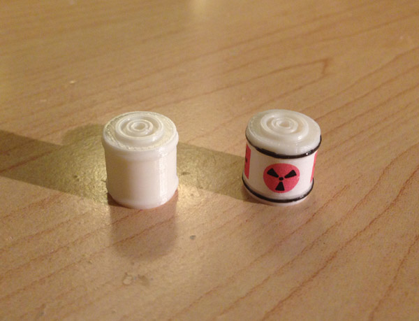
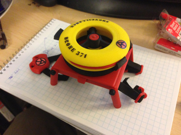
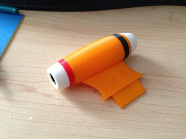
Here are the results:

tb3-engine-and-arm

I think my initial assessment of the color was a bit premature. It’s going to do fine.

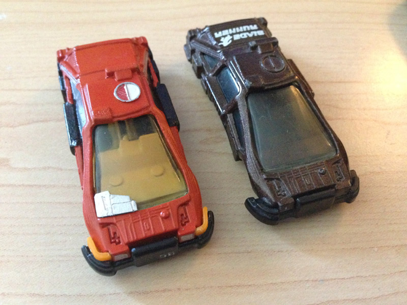
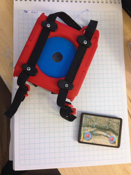
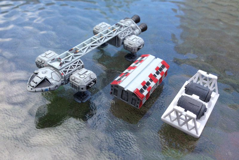
Next, I had to decide between the two reds I previously had, the Octave red, which is a brighter, more toy-like plastic, and the Afinia Premium red which is a darker red. This was a no-brainer because the red stripe on the bottom of TB3’s engine should stand out against the orange-red filament, and as I indicated earlier, the difference between that Octave red and this new orange-red was not great. So this picture shows the two reds together:

tb3-engine-rings-01

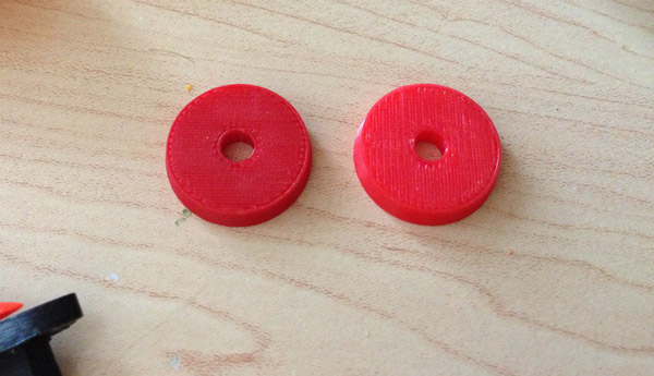
And so ultimately, I chose the Afinia darker red:

tb3-engine-bottom

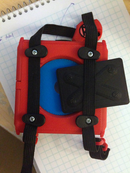
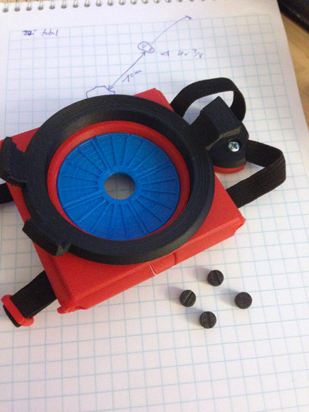
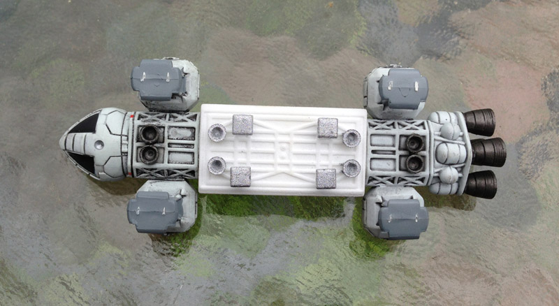
Here is the engine from the top. The black stripe has rods that protrude into the four intakes, and you can see the black here (though the picture is a bit out of focus.) I may lengthen those rods to bring them closer to the surface.  tb3-engine-top

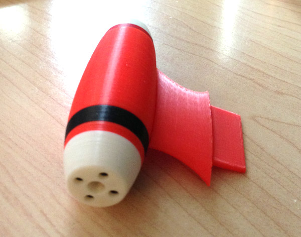
Update: July 13, 2014

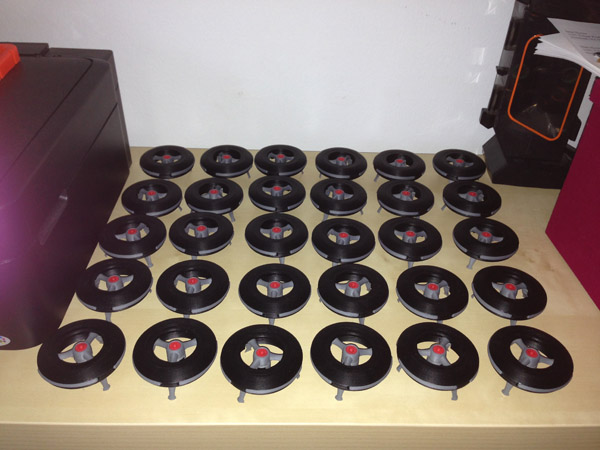
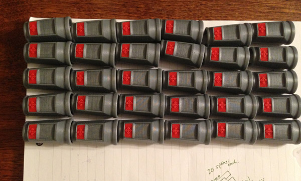
I just finished a fairly large 3D printing commission, 30 [redacted]s printed in 3 colors, in 15 pieces each, and one small screw. The last 10 went through the assembly line today.

Then I finished printing four rather long prints for a project at work.

So I was freed up to do some more of my Thunderbird 3 today.

I printed four engine posts (one safety) in red-orange, and glued the engine together.

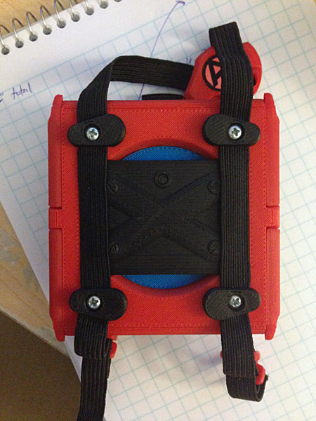
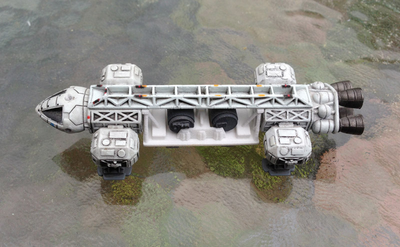
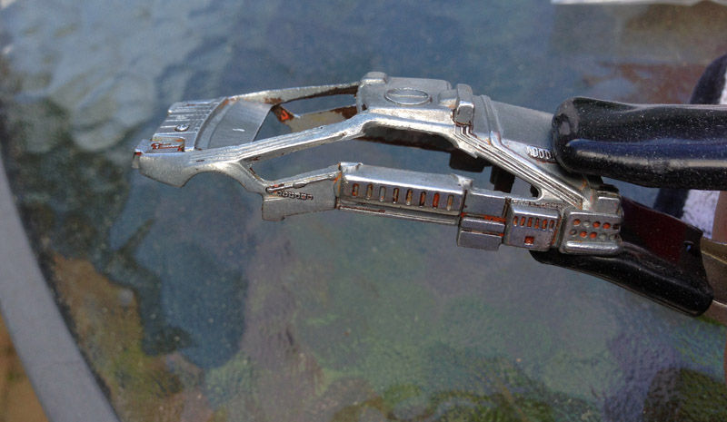
Here is the full engine assembly, from engine body to upper arm, shown fitted together.

tb3-engine-assembled-01

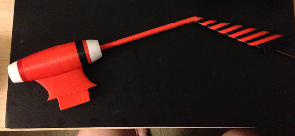
You can see one metal wire (a coat hanger segment) sticking out the top. A second one will go on there for stability. The wire above the arm will fit into the body for even more strength.

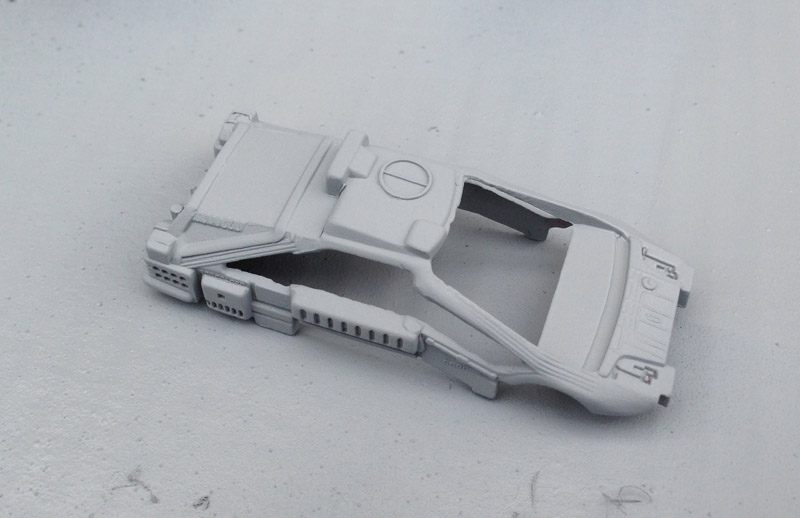
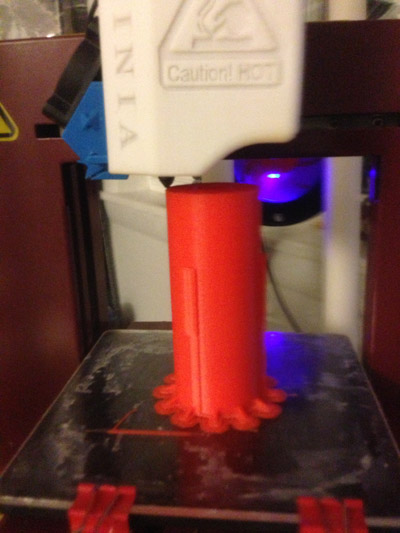
And here is the upper body section printing: (I apologize for the fuzziness. The printer was in motion so focus was impossible.)

tbe-body-section-printing-01

Here is the upper body section, printed, with the two wire rods in the arm, and one arm assembled (to the point of the post):

tb3-upper-body-and-arm-assembled-01

Update: July 14, 2014

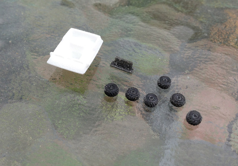
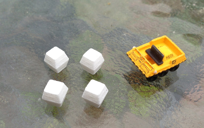
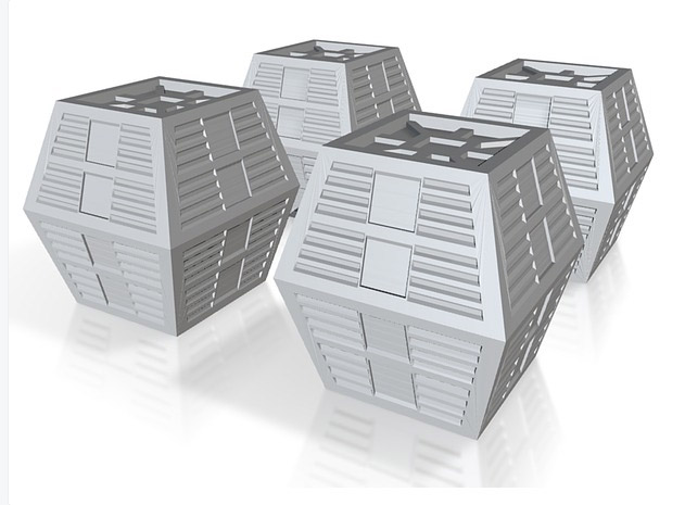
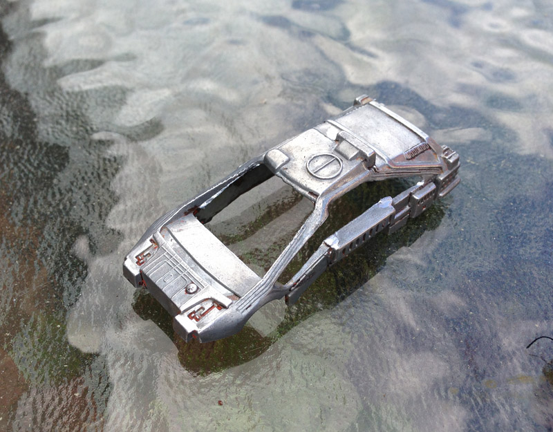
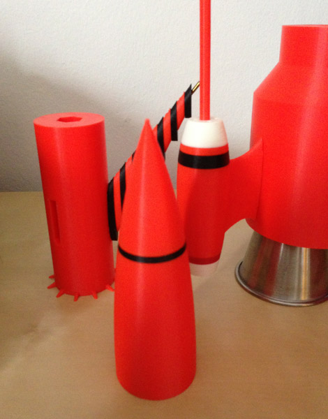
The printer was busy last night, printing the large, bulky base section of the rocket. This morning I printed the nose cone in two sections. (I already had the black ring printed when I did the arm pips.)

tb3-parts-01

The hexagonal openings are for a rod that I will use to fit the pieces together and ensure alignment.

tb3-nose-cone-assembled

Update: July 15, 2014

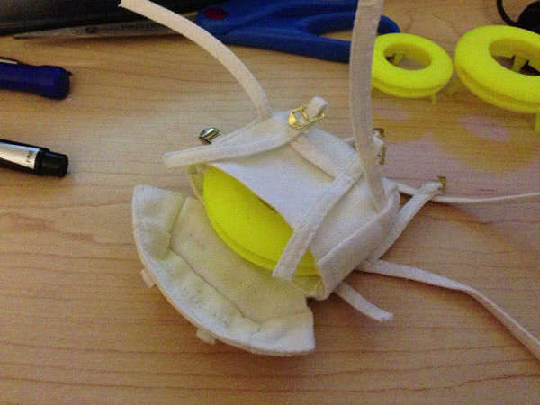
Last nigh I printed the docking ring, the yellow lower fins (though in the wrong yellow – as a test print I use my neon yellow), the central fins and central ring, and the connector posts. The only thing left to print is the bottom cap, and two more arms.

tb3-parts-02

And here it all is, put together, with one arm in place, though I haven’t filed down the metal post enough to fit the arm post into the arm yet. And the bottom cap is not yet printed.

tb3-test-assembly-one-arm

Update: July 16, 2014

Here we get closer to the end. The bottom cap is printed (showing the true weakness of 3D printing in layers, since it really accentuates those layers) and getting the other two engines printed.

tb3-parts-03

Update – July 17, 2014
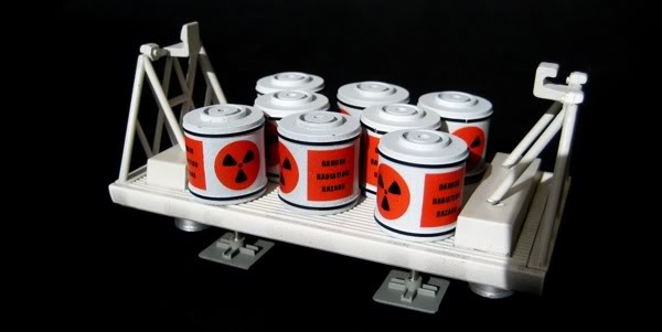
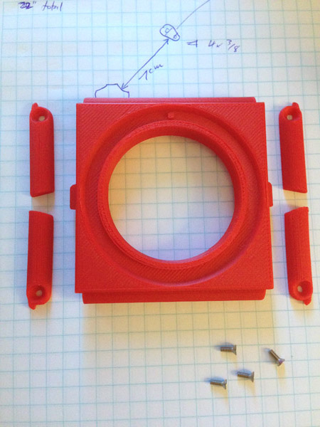
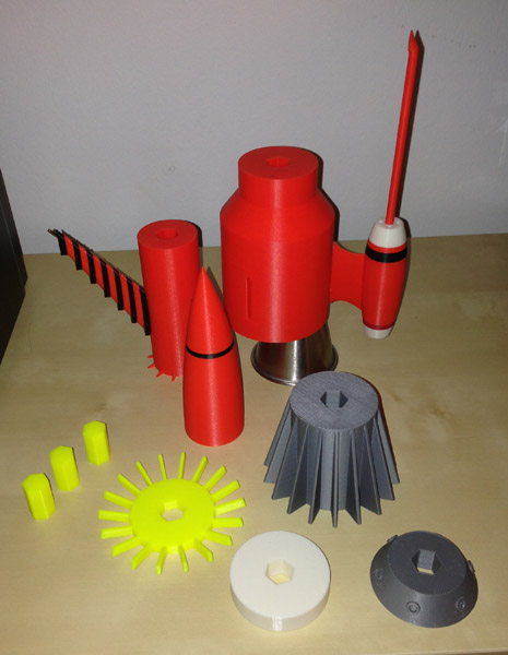
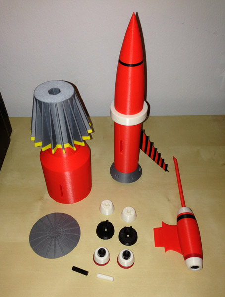
All parts:

tb3-all-parts-final

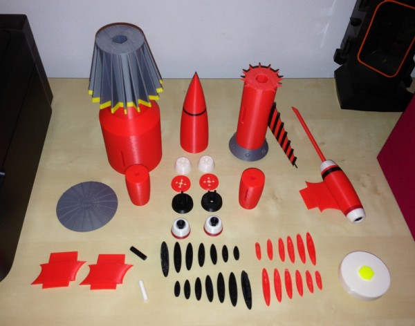
This is all of the pieces needed to make the entire rocket. One entire engine arm is assembled here, they just need to be joined. So let’s count:

83 parts. (Not shown are the other two arm posts. I forgot to put them in the picture.

BTW, The arm posts are interesting. My printer has what is generally considered a 5x5x5″, (just a bit over 12.5×12.5×12.5cm)  print volume. These posts are, in their final form, 4.85″ (12.3cm) in height. So I had a bit of room. But note their thickness. These are thin posts. Yet this printer was able to churn them out without deformity.

tb3-engine-posts

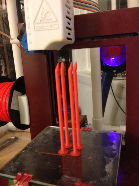
How this printing process works is a layer is printed down by a hot extruder head, melting plastic and pushing it out of a nozzle in exactly the same way a glue gun works.

Imagine that it’s trying to lay a layer down on existing layers that are 12.5cm tall, and the thickness of only .5cm! Nearing the top, just the act of laying down the melted plastic wiggles those posts quite a bit. Yet it still maintained its form. And they did not snap off the raft base. (I have had this happen.)

Color me impressed!

Update – July 19, 2014 – Morning

I printed the conical cylinder at the top of the vanes wrong. The intakes were at the wrong angles. With the hexagonal slot in the middle for alignment, I couldn’t just arbitrarily rotate it.

I checked my model and sure enough, I had modeled them at the wrong angles and never noticed. So I aligned them and printed the part again. Now the intakes were prefectly in line with the arms – which is wrong!

So I rotated them to be between the spans of the arms, and re-printed. But somehow I must not have unloaded and reloaded the model because I printed it a third time, exactly as I did the second, which was wrong!

I just got my Zen Toolworks Silver spool (my Inventables silver was becoming quite problematic, clogging at the low temperature, and becoming unmanagably hard to remove from the support material in the high temperature, and giving me an uneven flat surface) and printed it with the new filament. It printed right this time, and better than the older filament.

After doing that I test-fitted the three arms on the model, to make sure they fit. This is because I knew I would have to Dremel down the coat hanger wire that protruded from the arms to fit precisely inside the hole in the arm posts.

tb3-arms-test-fitted-01

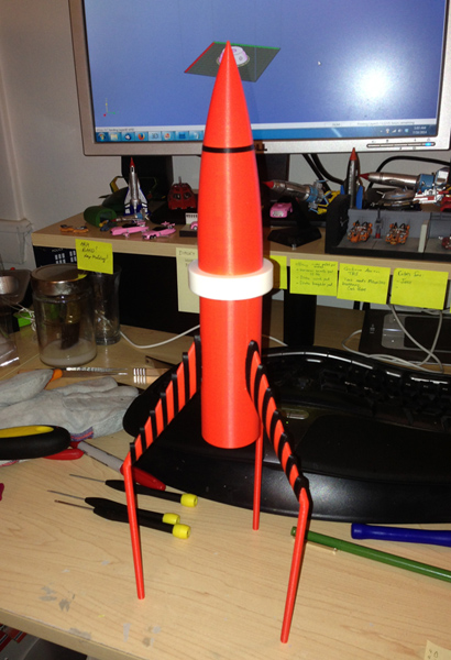
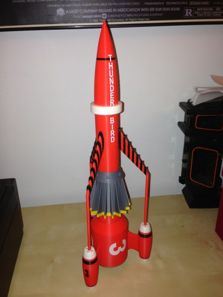
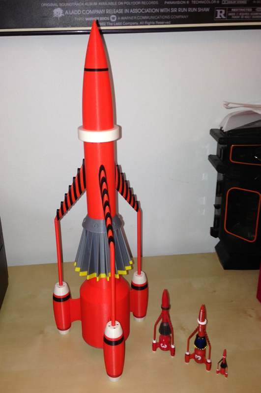
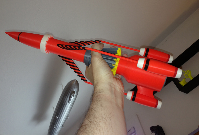
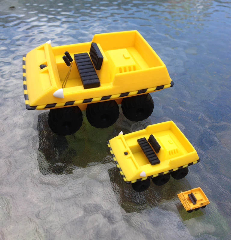
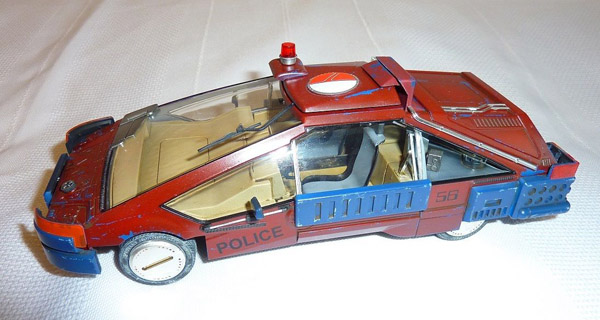
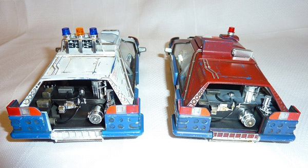
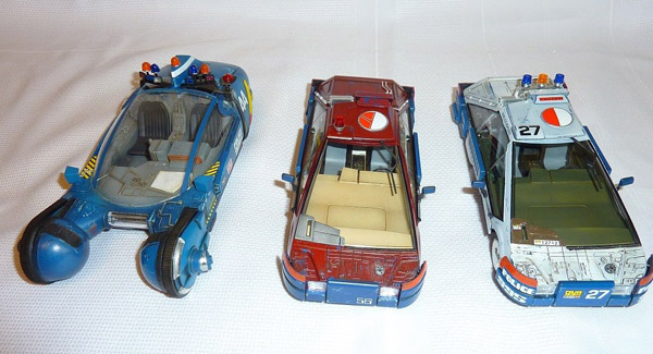
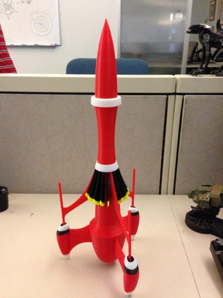
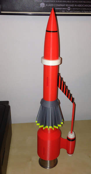
So this morning I assembled the whole beast, and I’m proud to show it off. Here it is, with several of its younger brothers. (Matchbox, Konami, and a very tiny one that comes with a Thunderbird 5).

tb3-complete-with-younger-brothers

And for Derek Trapp:

tb3-derek-trapp-tribute

Update – July 19, 2014 – Evening

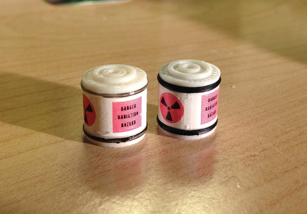
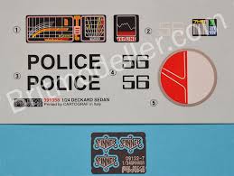
I bought some white Testors water-slide decal paper, which I have used in the past for small decals. I designed and printed the decals for Thunderbird 3. Since the rocket needs white text, this can only be printed on white decal sheets. Clear won’t do, since no printer prints in white ink.

So I had a clever plan to print the letters with orange in the background so I could cut the letters close to the edge and let some orange bleed over. This would look good and work. Sure.

The trick was in getting the incredibly thin, wet decals on the body without them folding up like sheets in a brothel. It was impossible.

But I also printed the black 3s (for the engines) on clear decal paper and that worked fine.

But what to do about the white text?

So instead of using decal sheets I went with glossy sticker paper, using the orange background idea. I carefully cut out the main 3s and the THUNDERBIRD, and stuck them to the body. They peeled up at the edges. Not permanent sticker sheets, apparently.

So I used some Elmer’s permanent bond spray glue and stuck them to the rocket.

The result isn’t bad. I couldn’t cut out the individual letters for THUNDERBIRD, since they would be too complicated, so I did HUNDER and BIRD as a block, with orange background. The T had to be cut out since it crossed over the black stripe, and had to look right doing so.

Anyway, the result was better than expected. Here it is, finished. (Well, there is some debate as to whether there is only one THUNDERBIRD going down the body or three. Some say three, so I will add the other two.

tb3-complete-with-decals


Shapeways Here We Come

Over the past month or so I have been experimenting with Shapeways.com. I had various models shipped to me so I could gauge how good they were, and if I could sell them.

I altered, perfected, ordered again, until I was confident enough to open up a shop which now sells some of my designs in some limited materials that I know work.

Here are some of the models now available in my shop:

Konami 4.5″ Eagle Winch Pod

shapeways-eagle-winch-pod-attached

Seen in the premier episode of Space 1999: Breakaway, the Winch Pod was used to lift and transport nuclear waste containers. I based mine on the Product Enterprise 12″ “Freighter Eagle”. It is not, in fact, a freighter pod. A freighter pod is a flat pod that is used to carry a number of the nuclear waste containers.

Here it is sitting next to the Rescue Pod that the Konami Eagle came with. Originally I had plastic spanning the top of the pod, thinking the walls on either end would not hold. Originally I was right. But when I modeled the diagonal struts, those walls became very strong.

shapeways-eagle-winch-pod-angled

This version is made of Shapeways “White Strong & Flexible”. It is a slightly grainy material, like a fine sand, but looks great.

I spray-painted the winch barrels in a gray primer. No further painting was needed, I felt. But most people will probably want to weather it with a black or gray wash to make it match the Eagle a bit better, and I’m sure that would work fine.

If you buy this from Shapeways (here) you will find that it is actually a bit too long. I did that on purpose. I had no way to be sure all of these Eagles were identically-spaced. This way, if it’s tight, you can file it down a bit until it fits snugly but not overly tight.

shapeways-eagle-winch-pod-assembled

Here is the underneath, painted with a silver spray-paint (rattle can). This could be done better, with a darker metallic gray for the jets, and a straight primer gray for the landing legs. But the bottom is fully detailed.shapeways-eagle-winch-pod-underneath

12″ Scale Stun Guns

12″ action figures like Action Man, GI Joe, Dragon Models, etc, are 1:6 scale. I printed one of these stun guns at 1:6 and it seemed a bit small, so these are more like 1:5 or 1:5.5 scale. But they look pretty good.

shapeways-stun-guns-x4-sfw

I sell them in White Strong & Flexible Plastic material, which is a bit grainy, like fine sand, but strong and it looks good. There are two files, however, if you want a set. Shapeways currently has no way of grouping everything into a single “product” or “project”. They are working on it.

The hand-grips glue in place, and make it so you don’t have to paint them. They look good in either Black Strong & Flexible Plastic, or Black Detail Plastic.

This set comes as two separate files. You need both:

Here are some of mine, roughly painted. I didn’t take a lot of time with them, and I didn’t clear-coat the white one before painting. That meant I got some paint bleed. But the silver ones worked better.

shapeways-four-stun-guns

I have to say, they look pretty good in the hands of an action figure, like my custom Doctor Who Brigadier Alistair Gordon Lethbridge-Stewart, (who is holding one, for some inexplicable reason.)

shapeways-stun-gun-held-by-brigadier

Moon Buggy Scaled for 12″ Eagles

AMT made a very nice 12″ model of the Eagle back in the 1970s. Some years later, ERTL/AMT made a reproduction of it, and now a new version is available using the same molds. Product Enterprise also made a very very nice version of the 12″ Eagle with various different pods. They even sold one set that had a laboratory pod, a tank, and a scale moon buggy. I wanted some of the moon buggies for my 12″ Eagles, so I made one:

shapeways-moon-buggy-parts

Unfortunately, the flat lighting shows NO detail in this photo, of the Strong White & Flexible Plastic version of my moon buggy.

This model comes in two separate files:

Here it is with a painted version. I’m not a professional model painter. I did this rather quickly in Testors yellow, and used a fine black sharpie to draw on the body detail. You will do a much nicer job, I’m sure.

shapeways-moon-buggy-with-finished

But even with my crude lines, this tiny beauty looks great next to my Eagle (This is it before I drew on the body lines):

shapeways-moonbuggy-next-to-eagle-model

Here it is with my 4.8″ version and my 2.3″ version:

my-moon-buggies

(I will be making decal sheets for the larger ones. Those were printed on my Afinia H479 printer.)

Cargo Crates for 12″ Eagles

These iconic double-trapezoidal crates are meant as props for your 12″ Eagles. They measure 6mm wide, and 7mm tall. The detail is there, but it’s so small it’s hard to see.

shapeways-crates-moonbuggy-12-scale

You get a set of four.


Cargo Crates for 44″ Eagles

These are also available at 20mm across and 22mm tall. Available in Strong & Flexible (and Polished) Plastic.

I haven’t got these printed at this size yet, but this is the 3D file as seen on Shapeways.

shapeways-20mm-crates-shop

Moonbase Alpha Landing Pads

The 1970s version of the Moonbase Alpha model kit was inaccurate in several ways, but it looked pretty good to me. One inaccuracy is that there were only 3 Eagle launch/landing pads, when there should have been 5. They were also over-scaled to fit the overscaled Eagle models that came with the kit.

shapeways-landing-pads-both-scales

I modeled a version of the original-scaled landing pad so you can buy enough to make up the difference. But I also added the detail of the docking tube.

I also modeled a version that was more accurately scaled to the rest of the moon base, which was about 80%.

The cross landing pad is raised slightly to help with painting or decal application.


A Note on Materials

Strong & Flexible Plastic is a grainy plastic, and as the name implies, strong, and has some flex to it, especially on thin parts or areas. Good for display, good for priming and sanding and painting.

Strong & Flexible Polished Plastic is the same material put in a sand polisher. This smooths out surfaces but means tinier parts may not print as well. If I’m selling it in my store, it means I’ve tested it on small parts, and I’m very confident on larger parts it works well. Some items may not be available in this material because of the tiny parts I model. For the Stun Guns, you can use the “Print it Anyway” check box. This removes any guarantee from Shapeways, but I did this with the Stun Gun bodies and they look great.

Detail Plastic. This is a plastic for better detail, but some tiny parts will not print in this material. I don’t make many things available in this material due to its limitations.


Deckard’s Car

June 8, 2014

When my favorite movie, “Blade Runner”, came out, ERTL put out a set of four die-cast Hot Wheels-sized vehicles from the movie:

blade-runner-ertl-4

The brown one second from the left is Deckard’s de-commissioned Police Spinner. Obviously it was not the standard Patrol Spinner, on either side of Deckard’s. But according to everything I’ve read while Deckard was a member of the Police, his car could fly. But not anymore. Not since he quit. Only police cars are supposed to be able to fly, I guess.

I have a few of these ERTL cars, in various condition. None mint. But recently Fujimi made a 1:25 scale model kit of it:

fujimi-deckards-car-1

What? It wasn’t brown. And had some nice detail. I bought the model, and intend to build it up maybe this summer.

But I thought it might be very nice to take one of the ERTL ones and paint it up and detail it more accurately than the ERTL version.

The hard part was drilling out the rivets to release the body from the chassis. I used a Dremel, and wasn’t overly delicate. I scraped the bottom a bit, but that’s not tragic.

Then I soaked the body in a jar of acetone for a week, and then used a Brill-o pad to scour the paint away.

OLYMPUS DIGITAL CAMERA

Then I primed it:

OLYMPUS DIGITAL CAMERA

Then I spray-painted it orange, with a rattle-can.

OLYMPUS DIGITAL CAMERA

I am a bit worried the can was not the best painting method. I just bought an airbrush with compressor so I may re-strip it and re-paint it with the airbrush.

More coming, including details on the modifications I made.

I believe I will re-strip it, because I also want to remove the two vertical window supports. They do not exist on the actual car. They are part of the window.

Update – June 22, 2014

Here are some photos of what I’m trying to achieve with this tiny version:

deckard-car-ground-01-small

deckard-car-ground-02-small

deckard-car-ground-03-small

deckard-car_57-small

When I originally painted the body, I didn’t yet own an airbrush with compressor. Now I do. And I decided, after looking at these pictures some more, that the very thick window uprights had to go.

So I stripped the paint down again:

Using a Brill-o pad, I scoured the paint off, after the body soaked in acetone for another week.ertl-deckard-car-stripped

Then I used my Dremel to remove the vertical window uprights on either side:ertl-deckard-car-posts-filed

When I polished that up a bit, it looked like this:
ertl-deckard-car-posts-finished

And then I primed it.

Sadly, I primed it in a 2x coat primer which was rather thick and chunky, so I stripped it a third time, and primed it with automobile primer:
ertl-deckard-car-primed

Then I used my new airbrush to paint it again. No pic yet. It’s still drying.

Stay Tuned.