GI Joe Adventure Team Action Pack – Airborne Surveillance

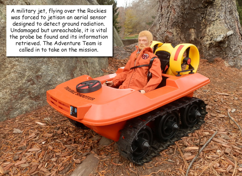
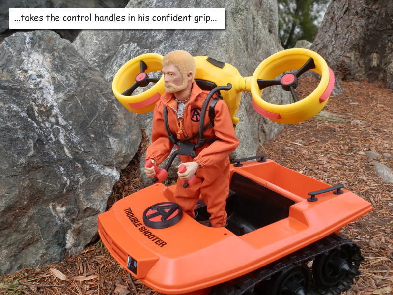
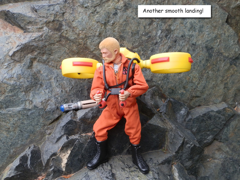
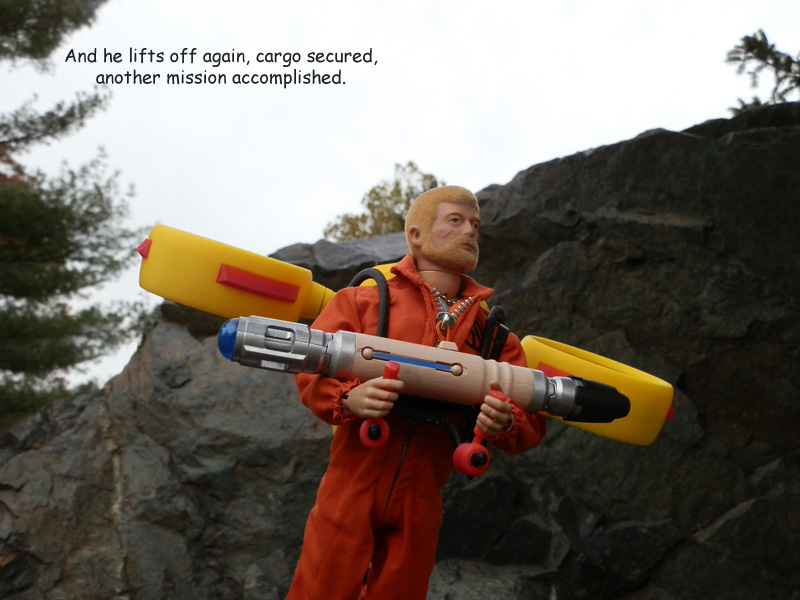
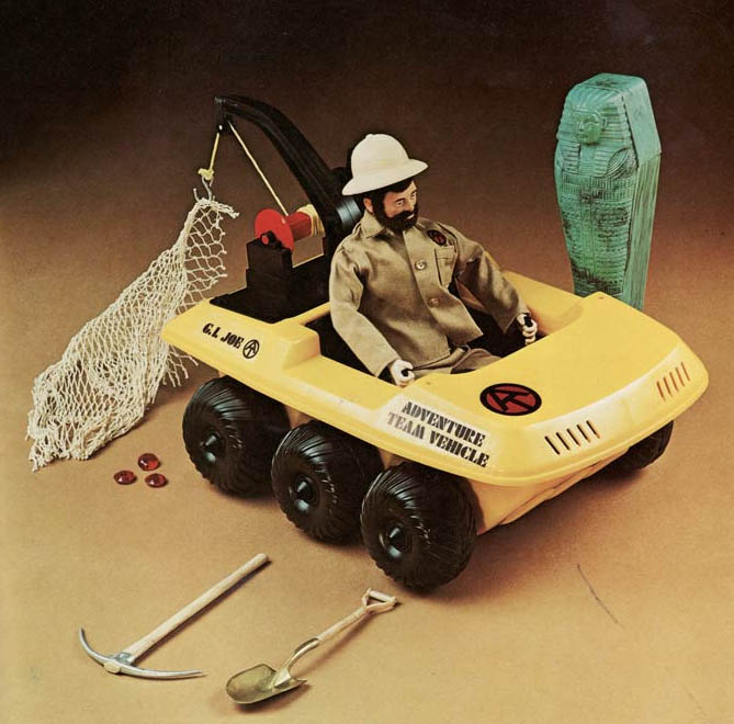
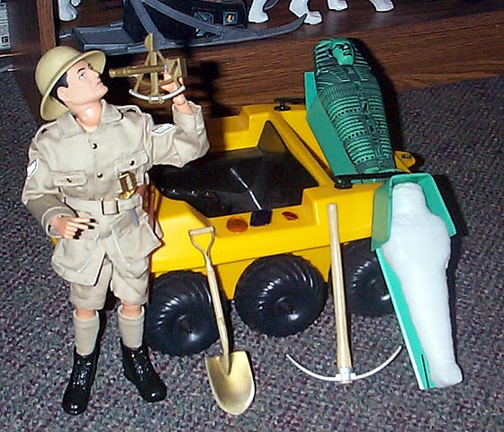
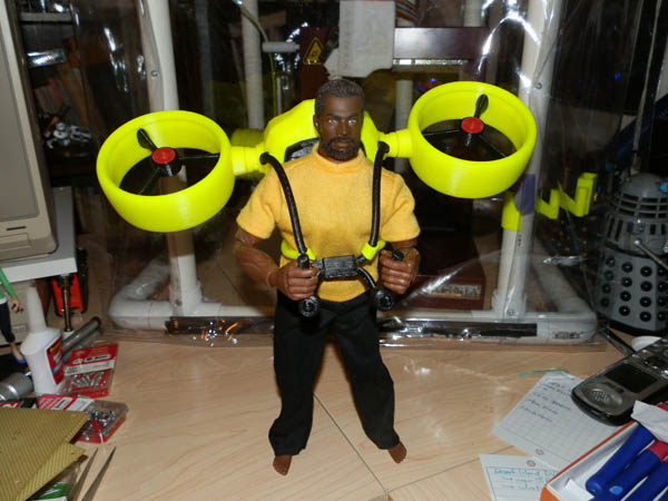
As my second GI Joe Adventure Team Action Pack, I decided to make a set that will again give the ATV a purpose. This set will snap to the back of an ATV or Trouble Shooter. This time, a rack will carry two remove aerial surveillance drones.

(The first Action Pack, a Jetpack, will also have an ATV component, but that isn’t printed yet. It will be a rack to store the collapsed jetpack for ground transport.)

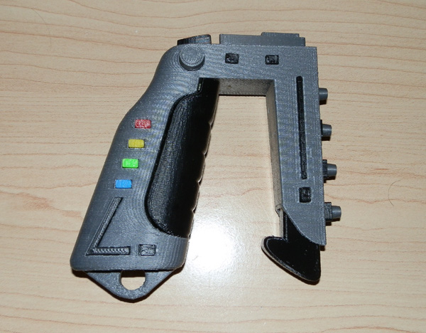
Also in the set will be a computer tablet touch-screen video mapping and drone control system on a flexible armature which will attach to the back of the ATV or Trouble Shooter, most likely slipping over the back ledge and onto the tow hook for support.

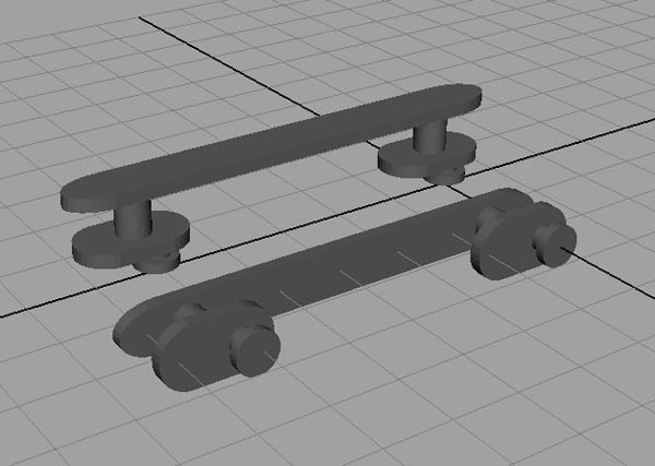
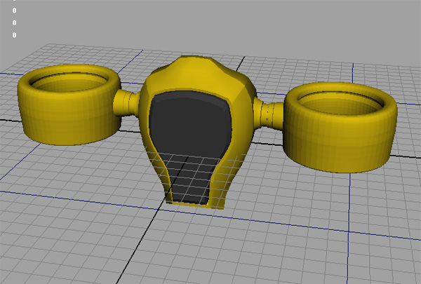
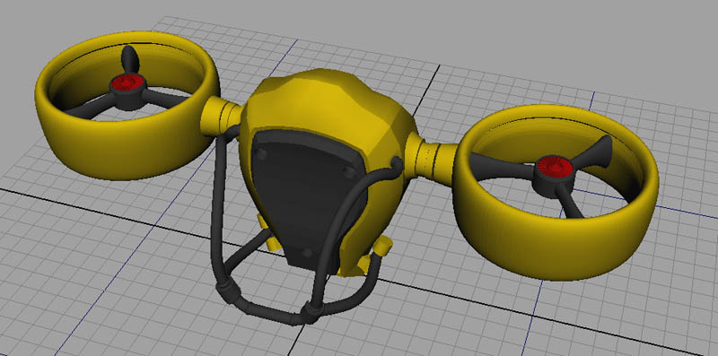
Here are some of my first images, from Maya:

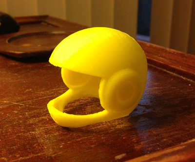
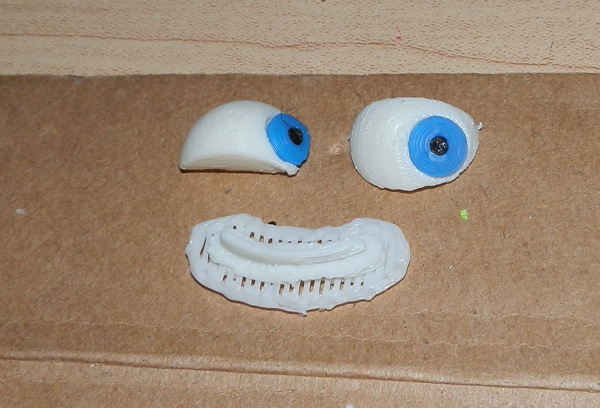
This is the top of the drone featuring a smooth ring-like body with a central hub and three bracers. You may be reminded a bit of the Jetpack design. This is on purpose. i want to have a consistent design aesthetic for these sets, and this is not an unfamiliar concept for science fiction aerial drones.
at-surveillance-prototype-1

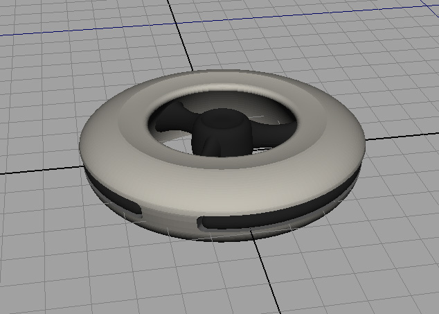
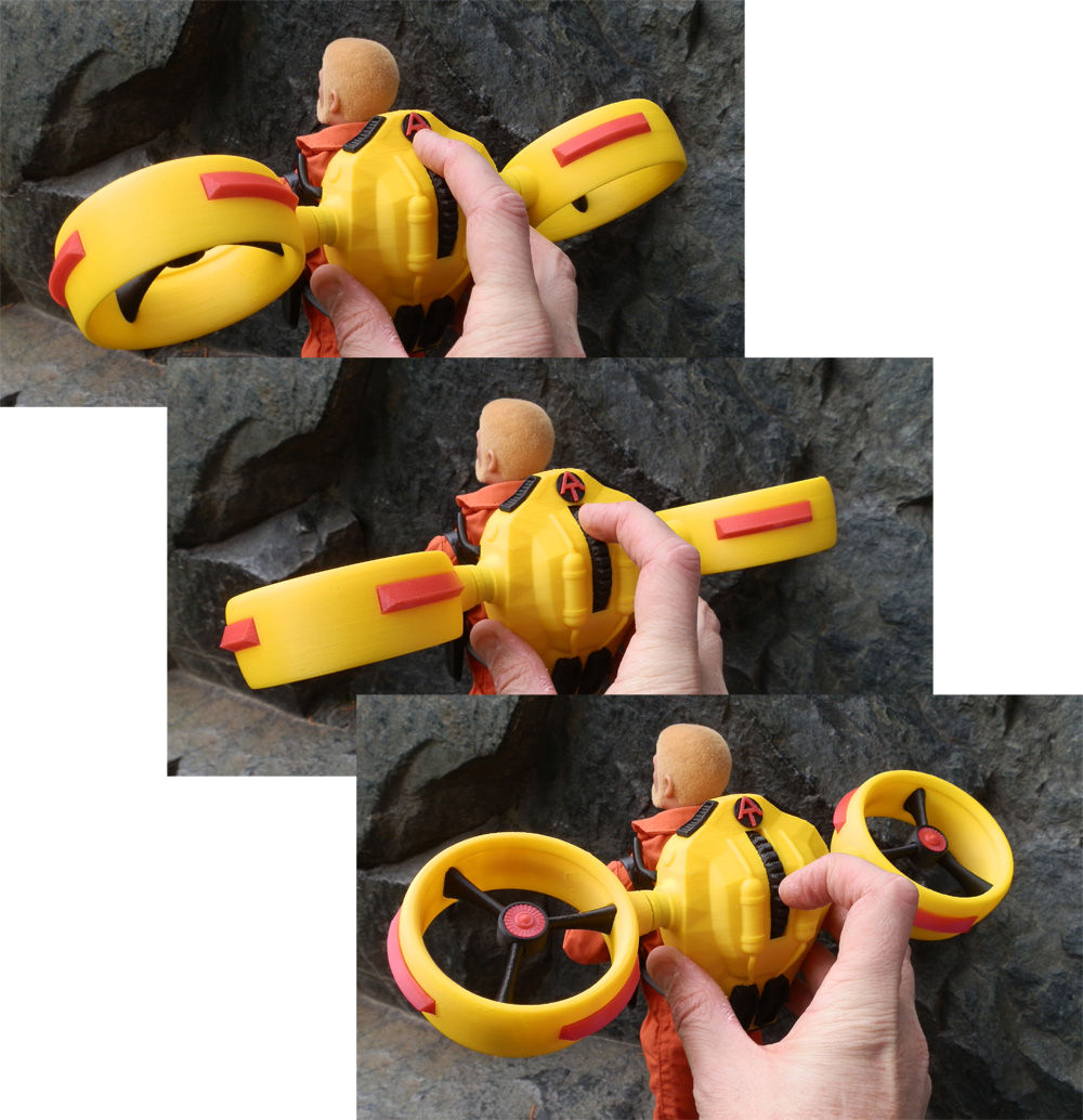
The three central struts connect to the hub, but the bottoms also swivel down to form a tripod of legs for landing.
at-surveillance-prototype-2

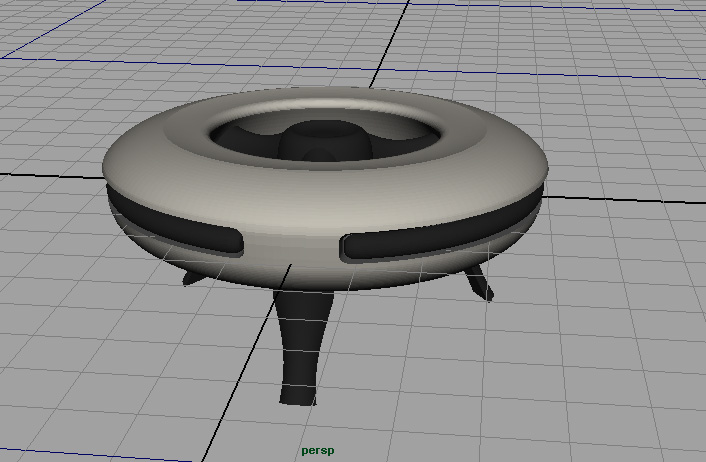
Since the surveillance camera dips a bit below the ring (for a full panoramic video image) the legs are necessary for a landing that won’t damage the camera.
at-surveillance-prototype-3

While the legs will swivel down on hinge pegs, the cuts to make this necessary are not yet made to the model above, so bear that in mind.

I will probably print the body in white with black detail, much as you see here, but I may put some color on them, perhaps make the central hub red. Not sure.

On the ATV itself will be a rack that snaps into the slots (like ATV rails or the winch does) and the drones will snap into two harnesses there. No concept yet of what that will look like.

Stay tuned. More to come.

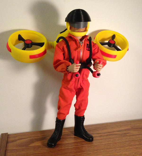
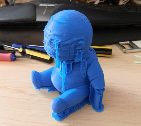
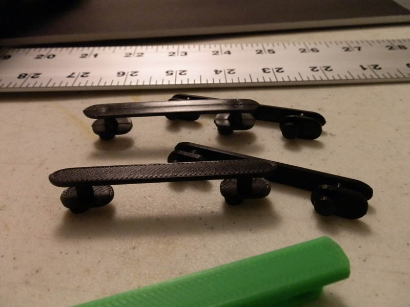
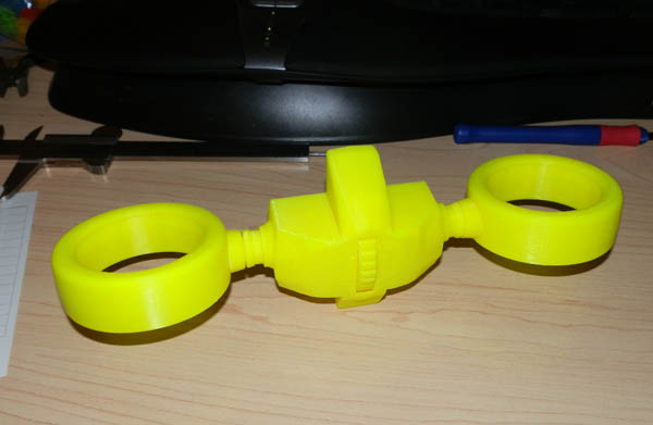
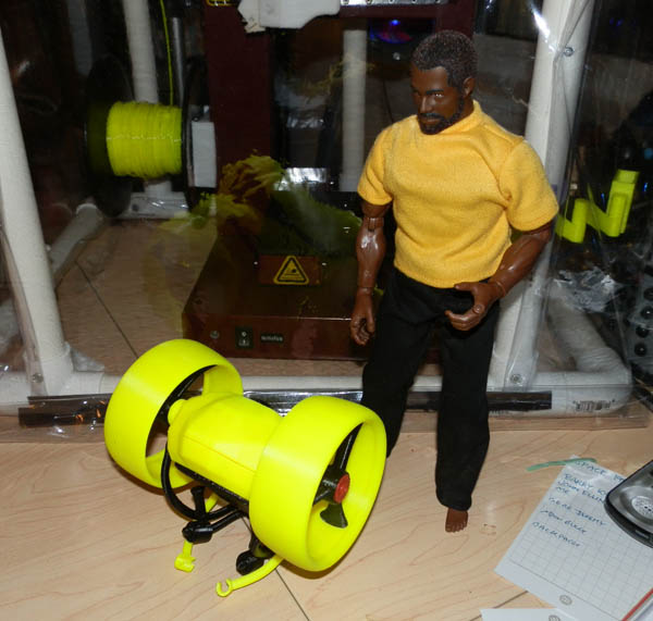
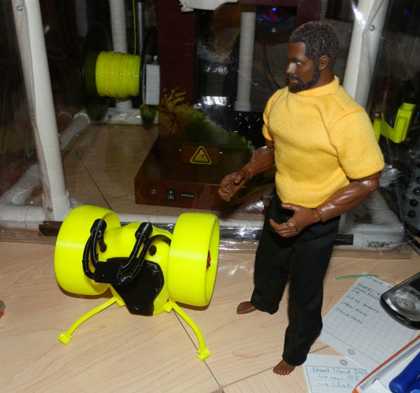
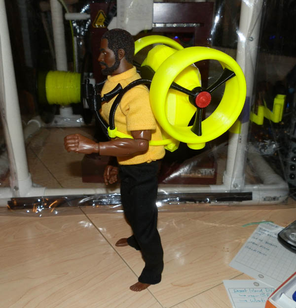
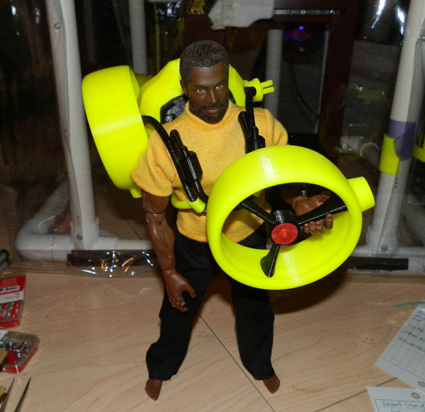
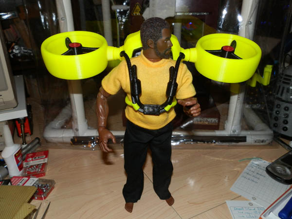
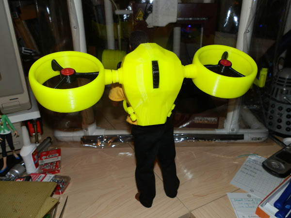
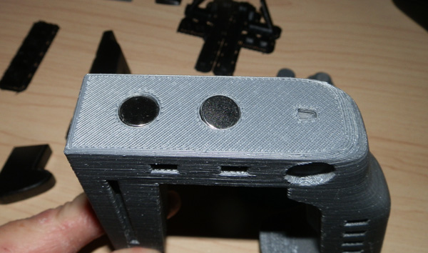
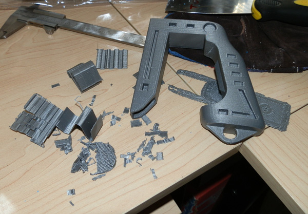
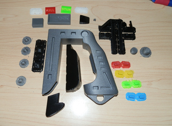
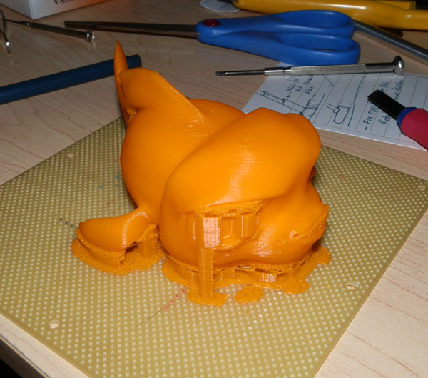
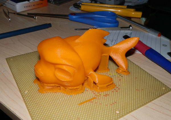
So here is the first prototype print. I think I will be changing the black insets to red, as well as putting a bit of red on the center of the hub.

OLYMPUS DIGITAL CAMERA

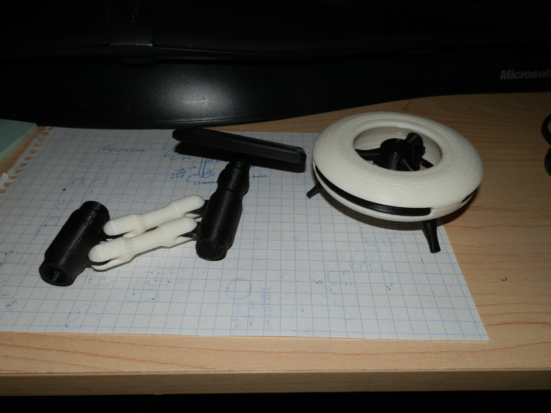
I have some refitting to do, the legs are a bit loose, and the camera is a bit small, but I think it’s actually 90% complete, and I just started it a couple of days ago.

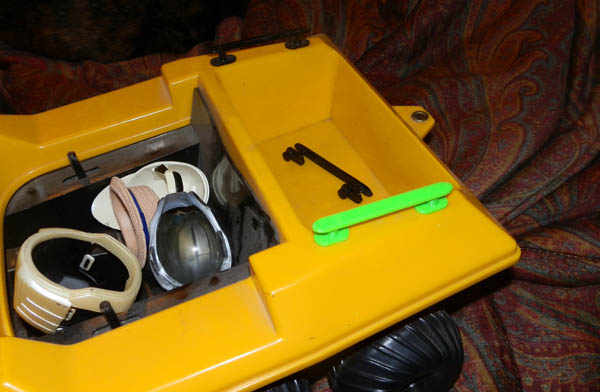
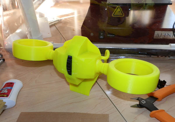
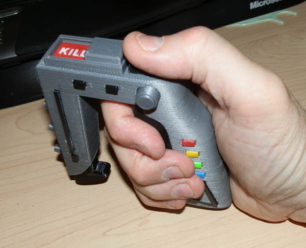
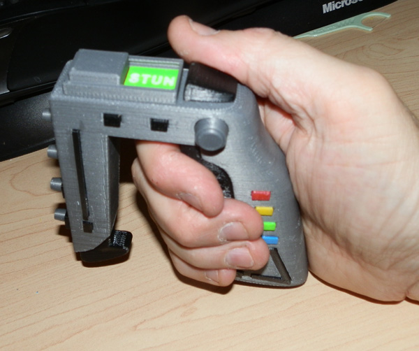
The armature will be mounted on the back of the ATV, and two harness racks will also mount there that the drones will snap onto.

A sticker will go on the screen, with a printed map and control interface on it.

Here is the sticker, which should be set to print at actual needed size:

AT-Surveillance-Touch-Screen-print

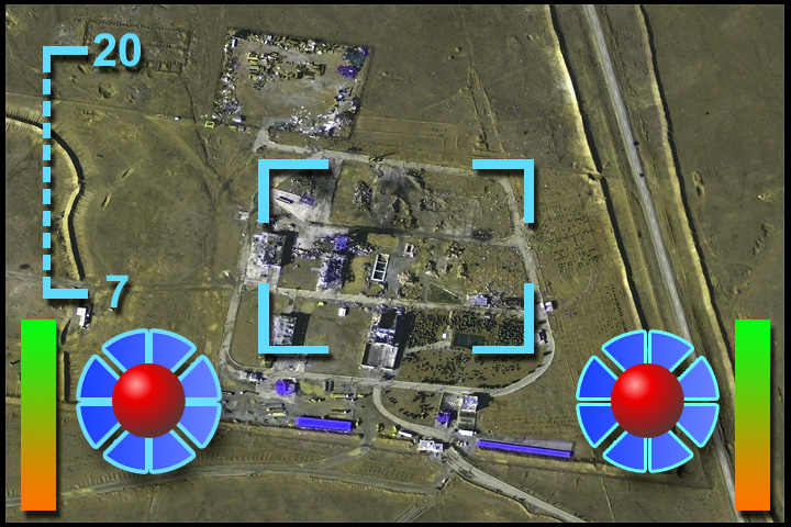
It prints so that when you cut away the black edging you are left with a 6cm x 4cm image. The black is printed just to give you some leeway so the edge you cut (which is always so hard to cut exactly) is black instead of white, looking like paper. You can print this on sticker paper to make it easier, or you can glue it to the screen. Glossy paper recommended because it’s supposed to be a glass touch-screen.

GI Joe Adventure Team Action Pack Jetpack – First Complete Print

After the prototype of my Jetpack was finished, I spent some time adding detail to the back of the jetpack and refining other aspects, such as how the jet arms attached, how much access you had to the thumbwheel, I was ready to print the final version.

I was approached by Afinia (the manufacturers of my printer) and asked if I had anything I wanted to show at their CES 2014 show coming up. I showed them the video of the prototype and they thought it would be very fitting for their show. I am readying this final print now to send to them for the show (along with a GI Joe to pose it with.)

At around the same time, I saw a posting by 3DAGOGO, a web site startup whose intent is to provide a market for designers to sell their 3D print designs. I signed up and noticed several contests, one of which is for Household Item and that includes toys, so when I showed them some of my designs, including the prototype video, they thought it would be a perfect candidate for the Household Items category, and encouraged me to enter their contest.

This weekend I shot the Jetpack in a sort of short photo story, intended to show off the various features, and I will be preparing the files for print so I can upload it to their contest, and perhaps to sell as a design there.

I also shot a second video, this time of the first finished print.

So here it is, the first photo story I’ve done in years, and I did it just to show off the awesomeness that is the new GI Joe Adventure Team Action Pack Jetpack!


OLYMPUS DIGITAL CAMERA OLYMPUS DIGITAL CAMERAOLYMPUS DIGITAL CAMERA OLYMPUS DIGITAL CAMERA OLYMPUS DIGITAL CAMERA OLYMPUS DIGITAL CAMERA OLYMPUS DIGITAL CAMERA OLYMPUS DIGITAL CAMERA OLYMPUS DIGITAL CAMERA OLYMPUS DIGITAL CAMERA OLYMPUS DIGITAL CAMERA OLYMPUS DIGITAL CAMERA OLYMPUS DIGITAL CAMERA OLYMPUS DIGITAL CAMERA


And to show off the thumbwheel, (which I do in the video) I took a series of three photos showing the thumbwheel in action:

thumbwheel


Update – Nov 19, 2013

The helmet I designed to go with this jetpack was fun to model. I made a highly-tesselated sphere and used a lattice grid to shape it until I got a fairly pleasant shape. I hollowed it out using measurements of a GI Joe head, and did a test print. It didn’t fit. It also printed fairly badly because it’s completely round. I want it to look its best, so I printed it with the back of the helmet as the floor of the model.

With current 3D printing technology, the floor of the model is supported by a raft and scaffolding material to lay the base of the model on. On a rounded model, this causes some very ugly ringing, so I figured it would be fine at the back, and it is. But I still want to improve it.

Here is the first test-print. (The ringing on the back is not visible.)

at-jetpack-helmet-first-print-yellow

Then I modeled a visor cap and a “virtual vision” visor – (the thing is not see-through, but uses enhanced virtual 3D imaging to see), and printed a version in red (because my printer wouldn’t extrude the yellow due to a head clog which I fixed by replacing the head.)

at-jetpack-helmet-prototype-red

Then I printed a yellow version with black visor cap and silver visor:

at-jetpack-helmet-finished

And here is how it looks worn with the jetpack.

at-jetpack-with-helmet

Support Apps for 3D Printing

For the moment I can’t print a 3D model from my iPhone or my iPad or other mobile device.

However I have found a couple of ways that an iPhone or iPad (or mobile device) can be of help in the print process.

iCam

After one reel of filament failed me (it was inconsistent in thickness, which happens rarely, but is not unheard of) 2 hours into a 5 hour print, clogging inside the extruder head, I felt I needed some way to monitor the printing process without having to run up and down the stairs every few minutes. Normally prints just work. But I still feel the need to see the progress just in case bad things happen.

For example, during a recent print the scaffolding supporting a part of the model that stuck off into space cracked and fell over. I saw it in time to pause the print, superglue the scaffold back into place and rescue my print.

So I felt I needed a Nanny Cam for my printer. I went looking for something to fit the purpose. I found iCam, which runs server software on your computer which takes the output from your web cam and plays it on your iPhone or iPod.

Before this I had built a fume hood for my printer. Later, I printed an armature for my web cam that could be snapped to one of the upright struts on my fume hood.

It’s designed to fit the Logitech Pro 9000. The tail fits into the square cup, while the rounded cuff fits around the upright strut of my fume hood:

Now I can monitor my prints at any time on my iPhone and my iPad.

2013-10-24 19.54.30

So now I use my Nanny Cam (as my wife coined it) to keep an eye on the print without having to run up and down stairs all the time.

Clock

The one thing the Nanny Cam can’t do is tell me how much time is left in the print. I thought of hooking up a second web cam to just monitor the count-down timer on the Afinia print software, but duh… iPhones have an app called “Clock” which can be used as a countdown timer.

So I use that.

I set the countdown timer to a few minutes before the print should end (by Afinia software estimate, which is usually fairly accurate.) That way I can be in the room when the print ends so I can be there to set up another print immediately.

It prevents wasted time.

The Print Shop Is Open! The Printer Printed The Part It Needed!

This past weekend my printer showed signs it was slipping. The X axis (which moves the bed back and forth) slipped, which showed in one small piece I printed. It weirded me out, but I passed it off as an anomaly.

I printed another piece and it shifted the raft layer a bit. Now I was worried.

So I printed a couple of other pieces without issue. Then I printed a Plush Russ, which is a model of a plush figure, modeled by one of my co-workers as a caricature of another of my co-workers.

This time, 3 hours into a 4 hour print, the bed slipped again.

failed-print-01

You can see at the neck level the whole print shifted.

So I printed it again hoping it would finish. But no… this time it did the same thing at about the same level, only after that, it printed very badly for the rest of the head.

OLYMPUS DIGITAL CAMERA

Yikes!

So I contacted Afinia. They sent me a document on changing the bed heating element (because it showed how to open the X-Axis arm.)

Side note: I feel partly responsible for the existence of this document. The printer spent a few weeks on the road last month getting a new bed heating element. When I asked if they had a document on changing one out they said they did not. They had previously sent me a doc on unclogging the print head, but they didn’t have one on replacing the heating element.

Now they do.

Anyway, I opened the X Axis arm and saw this:

OLYMPUS DIGITAL CAMERA

Ah. Yup. That would do it. That plastic piece has teeth that grip the belt, sliding the print bed back and forth. It broke.

So Afinia said they would send me another one right away, which they did.

It is important to note that in the Afinia software directories is a directory filled with spare parts for the Afinia printer. A lot of the internal parts (as well as the protective print head housing and the fan housing and the filament feeder, the reel holder, etc, are modeled and printed on an Afinia printer.

Of course I could print my own replacement part. But with this part broken, I couldn’t.

But that same day Afinia sent me the part I realized that the break was nice and clean, so I tried a bit of superglue, and the glue held. Nervously I set the printer up and set it to printing this replacement part.

It printed! The whole thing. Without issue!

So I cleaned up the part, re-opened the printer, and removed the broken part (which was still nice and solidly held by Superglue) and replaced it.

That’s right. My printer repaired my printer. Again.

So the very next thing I did was print 9 parts that looked to be integral to the function of the printer and put them in my Afinia tool box in case another part breaks.

And the replacement part arrived today. Thanks, Afinia! I’ll hold onto that one as well in case I need it. I appreciate your swift, helpful action. Again!

I can’t tell you how much I love this machine!

The Print Shop is Closed – Yeah, So That Happened

For the past two days I noticed some slippage in the front/back motor mechanism of my printer.

I first noticed it on a small print. Part of the whole print just shifted about .25cm.

Then later I noticed it shifted during the raft printing, in the first few layers.

I hoped it was an isolated incident (or two) but then I started a 4 hour print of a small figure:

failed-print-01

At about 3 hours, the print bed slipped backward just about .5cm. The rest of the print went fine, but the damage had been done.

I printed a few smaller items after this with no problems. I made sure I used the software’s maintenance window to move the bed back and forth to see if I could catch any problem. It looked fine. So I printed a few small things, and they all worked ok.

Then Sunday morning I decided perhaps it was just a momentary problem and it had worked itself out. I re-printed the figure.

As you can see, at around the same place it slipped again. The height is not likely the issue because the first two slippages happened far lower in the model.

OLYMPUS DIGITAL CAMERA

But what’s particularly disturbing in this case is that it slipped twice, and after the slippage the print just went all to crap. It seems to be a progressive problem now.

I will try one more test print tonight, but nothing that’s going to take 4 hours.

Looks like she’s goin’ back to the shop again.

Now, some may think: “I told you. This tech isn’t ready yet”, I hear ya. However, when I opted to buy into a 3D printer at this fairly early stage in its development for the home, I knew full-well what I was getting into. I knew I was basically beta-testing the technology, but hey, I bought in figuratively and literally. I do not mind being part of the crowd that helps perfect this technology.

In a few years I expect to be printing in much higher resolution, with no support material, and in multi-colors. I expect the 3D printer progression to be similar to the home paper printing progression. Right now we’re at the dot-matrix stage. It won’t be long before I have a color laser printer (like I actually do for printing on paper.)

Project: GI Joe Adventure Team ATV Rails

The GI Joe Adventure Team ATV is a six-wheeled all-terrain vehicle loosely based on the Amphicat from the 1970s. It was sold with various wonderful adventure sets, but the best-known is the “Secret of the Mummy’s Tomb”.

secret-of-the-mummys-tomb

Here you see the ATV with a winch in the back. The winch slots into four holes in the back of the ATV’s body. When the winch is not in place, there are usually two rails for carrying cargo:

rare-gifts

Here’s a pair of them, alone:

atv-rails-set

These often went missing. So I’m trying my hand at reproducing them using the Afinia 3D printer.

I’m almost out of black filament at the moment, so I’m test-printing them in green.

Here’s the first model:

atv-rails-test-01

I decided to try printing them in this orientation to see which would work better. Because the additive 3D printing process prints in layers, and in the upper left version there are large areas suspended above nothing, rafting and support material will have to be printed. The one on its side would require minimal support, but the rounded edges on the underside might suffer from the support that does print.

How I’d print these best depended on this test print.

Turns out the side-ways version was bad. There were a number of issues that I thought would be minimized printing it on its side. I was wrong.

And it turns out removing the rafting from the upright version was not as bad as I thought and the result was a far better product.

And here’s a first test-print, attached to the ATV:

OLYMPUS DIGITAL CAMERA


Oct 28, 2013 – Update:

I have now printed several sets of rails and I have found that the cleanup is hard. Cleaning material around the smaller pin is risky, and often breaks the pin, but I usually end up with enough good ones to make it worthwhile.

Here is a photo of some of the rails:

OLYMPUS DIGITAL CAMERA

The originals are at the upper left, closest to the ruler. They have a mold seam running down the surface. The prints do not. They have a diagonal hatching which comes from the print method.

Mine are sharper-edged, (a result of not rounding the model) but I like it. I don’t think I’ll shoot for 100% accuracy. I’m happy with them as they are.

Also, note the longer green ones. Those are my first custom rails, printed in green only as a test. But they turned out rather nicely, and show that I can really go crazy making different rails.

Here is a photo showing the differences between the original (again, top left) and the 3D printed replicas:

OLYMPUS DIGITAL CAMERA

Today’s Project – My GI Joe Backpack Jetpack

I spent some time on my GI Joe Adventure Team Backpack Jetpack (too long a name, and in fact is probably not even a jet pack, since it’s using Dyson-like fan technology. But on the other hand to get the air to move fast enough, there has to be at least one small jet engine inside.)

Here’s where I left it with my last post:

atjp-01-rough-shape-01

So I began printing. I cut some pieces out of the back piece to save print time. I printed the thumbwheel, two engine shafts, and two engines.

OLYMPUS DIGITAL CAMERA

The yellow thumbwheel turns the two engine housings.

Here, you see the front attached, and the thumbwheel was replaced with a black one (after a minor revision):

OLYMPUS DIGITAL CAMERA

It’s Super-glued in place at this point.

And here’s a test figure wearing the backpack with a harness slung over him. I’m pretty happy with the harness. It fit on first try. I modeled it on a wing and a prayer, and I was a bit surprised to see it work so well.

OLYMPUS DIGITAL CAMERA

The harness will need two lower pieces to keep the backpack in place on the figure’s torso.

After I saw the engines on the backpack, I decided they were too thick, and not large enough. (The engine wasn’t fully printed. To save material and time I shortened them vertically. I still thought they were too stubby.)

So I remodeled them to be thinner and bigger. Here is my test pilot with just one of the newly remodeled engine housings:

OLYMPUS DIGITAL CAMERA

I also changed a few things in the basic design that aren’t immediately obvious.

For example, to keep the harnesses in place, I initially designed the clips on the lower harness arms that grab the upper harness to clip from the inside, so pressure would keep the arm in place. But it was awkward. So I changed it so the arms clip in from the front. They should still hold solid.

The hinge point for the lower harnesses was a bit of a problem. I wanted them to be strong, but I had to fit a T-shape tube into an upper and lower hinge, which can’t be done in a single piece hinge. And I experimented (in my mind and on paper) with several ways to do this. Then I realized at this angle, I could model the lower hinge piece on the front part of the backpack and the upper hinge piece on the back part of the backpack, so when I assemble the pieces, I can fit the harness arms in. (I have yet to print a revised body, but when I do, I’ll post results.)

ALso, originally the engines were supposed to be screwed to the shafts (or glued – I wanted this to be very close to a production type toy, so I modeled it to be screwed together for easy disassembly if needed.)

I changed the shaft ends so they aren’t just cubes. Now they are forked snap tines. They fit into the engine with a snap and the engines will be tight, but they can be removed.

I also recall that the GI Joe Action Pack backpacks also generally broke down from their fully functional state to something easily worn on the back.

So I changed the engines to be more than just a circular housing. I put a hub in the center with spoke bracers. The reason is that I can remove the engines and snap them to the shafts by the hub and the backpack can be carried easily. The forked snap tines will serve dual purpose.

atjp-01-model-close

I will be adding modeled detail to the outer rims of the engine housings and on the body.

Also, there is a rather clever (I think) control handle system coming. It will be attached to the flat bottom part of the harness, and hinge down for use and up for storage/carrying.

Update – Oct 7

As of this morning, printing a few extra parts to make the second engine, I’m ready to reveal the first prototype of the Adventure Team Jetpack Backpack.

Here it is, folded on the floor, ready for use. Like the Action Packs of the original Adventure Team era, the concept was to fold up to be carried. The two engines have hubs that snap into the same arm tines that the engines themselves fit into, for a compact, carryable shape.

OLYMPUS DIGITAL CAMERA

Note that I hope to also model and print a storage rack for a standard Adventure Team ATV, much the same way the winch attaches to the back.

Here, you see the harnesses open and ready:

OLYMPUS DIGITAL CAMERA

The upper harness holds the control arms, which are on a hinge.

Here, our test pilot wears the backpack to show that, like the Escape Car, it is large and possibly heavy, but completely wearable. Note: the two lower harness arms will eventually be in black.

OLYMPUS DIGITAL CAMERA

Obviously he couldn’t attach the engines while wearing it, so his assistant, (just off-camera) here detaches the engine’s hub and hands him an engine just before attaching it:

OLYMPUS DIGITAL CAMERA

Then the assistant attaches both engines:

OLYMPUS DIGITAL CAMERA

Here we see it from the back. (The thumbwheel allows you to tilt the engines in a realistic way.)

OLYMPUS DIGITAL CAMERA

Our test pilot swings down the control arms. The joysticks can be adjusted inward and outward slightly, though the curved arm makes a lot of adjustment impossible. I may have to straighten those for better adjustability.

OLYMPUS DIGITAL CAMERA

I do have a few planned revisions, like adding a bit of nice detail to the body, including an AT logo that will be printed in black and red and inset into grooves custom-shaped to fit them.

I also have two sets of lower arms. The body of a vintage Joe is a bit thicker through and the lower arms will need to be a bit longer for a vintage Joe compared to a modern Joe. But depending on what clothing Joe will wear while flying it, it may be better to use the slightly longer arms anyway.

It is currently printed in hi-vis yellow, which is a color I got with my printer that I’m not overly fond of, so I use it for test prints. This one actually doesn’t look all that bad in hi-vis yellow. But I’m planning on printing the second version in a more typical AT yellow.

Well, there you have it. My first prototype GI Joe toy.

Space:1999 Stun Gun v2.0

After printing the first version of the Space:1999 Stun Gun I noticed a few issues.

OLYMPUS DIGITAL CAMERA

First, the front bar was too short. The silver part should dip down to about even with the bottom of the hand grip. The black pommel should protrude below.

There were other issues including the switch length, the panels for KILL and STUN which I decided to do using inlaid text on red and green plates which has the letter spaces cut out to allow white printed letters to be put in place.

Here is the switch assembly in parts:

OLYMPUS DIGITAL CAMERA

The letters do this odd thing whenever my Afinia tries to print small solids. If they get too small, the Afinia seems to print the outer edges without trying to fill the interior until the letters get big enough and then they print rather better.

But these letters are TINY! And here they are glued into their slots.

The switch, seen here upside down, has a cup modeled in it to hold a rare earth magnet that’s about .95cm in diameter.

Here, the magnet is in place, resting on the two colored panels, sealed in by the switch’s rails.

OLYMPUS DIGITAL CAMERA

Then I put two more rare earth magnets in the main gun body, one underneath the “KILL” and one underneath the “STUN” panels.

OLYMPUS DIGITAL CAMERA

I then glued the switch housing in place on the top of the gun, sealing the magnets in place. Then I glued a magnet into the switch’s slot and shoved the switch into the rails of the switch housing.

When fully assembled, the switch does a very strong “snap” from one setting to the other because the magnet in the switch is very strongly attracted to the closest magnet to it, whether that be the one under KILL or the one under STUN.

Here are some photos of the gun in my hand:

OLYMPUS DIGITAL CAMERA OLYMPUS DIGITAL CAMERA

Here is a short, poorly-lit video I did to show off the gun and its functioning switch.

Here is a gun body hot off the printer:

OLYMPUS DIGITAL CAMERA

Note that it prints a fair amount of scaffolding material up the sides. This is there to build support for roof sections of the small holes I use to inlay the various pips on the gun. In a future version, I will try to model those with 45 degree slanted roofs to avoid scaffolding altogether.

Here is some of the plastic I cleaned up:

OLYMPUS DIGITAL CAMERA

And here are all of the parts required to build one stun gun. If you count individual text letters, which I do, there are a total of 47 individual pieces, not including the 3 magnets I use to make the switch feel awesome to flip. (Some pieces are connected together in this picture by the rafting they are printed on. I did this to keep track of them. As the small black pips are very similar, I need the layout to remind me which is which.)

OLYMPUS DIGITAL CAMERA

What Now?

This gun is still a work in progress. I am very happy with the results, but because I wasn’t 100% happy with the silver filament, I’m planning on trying one in gray, but I don’t have any gray at the moment. I will try some later.

But besides that, I intend to make a Commander’s Special, which is my own variant which will be printed in white, with most of the rest being the colors you see here, with perhaps the exception of the switch housing and maybe the switch. Since white and yellow won’t necessarily read, I may change yellow to orange for the orange pips.

Also, one of the first things I get asked is “what’s that black thing in the bottom front.” I dont’ really know, but I always imagine it to be a removable battery or energy magazine. It’s never really referred to in the TV series. But if you bought the “Moonbase Alpha Technical Notebook” back in the 1970s (which I never did and always regretted not buying) it is revealed that this is in fact the Bergman Cell, a battery to power the gun.

I intend to further augment this model to allow the energy cell to be removed. It will be held in place by smaller rare earth magnets if I can arrange it.

I also intend to figure out a way to make the trigger work. That is, it will depress, probably using two more rare earth magnets, this time to repel each other, for a spring-like feel.

More on this if I ever get to it.

More on that when I do it.

Oh, and here is a scan of the pages referring to the Stun Gun (Model 2) from the “Moonbase Alpha Technical Notebook”:

2005 2004


Bert The Fish

One of my co-workers created a fish for her demo reel, a 3D animated goldfish, which, if I’m to believe her file name, is called “Bert”.

She asked me if I could print Bert for her and I said “I’m pretty sure I could.”

Bert had some issues. The first version suffered from thin fin. The pectoral fins were a bit too thin to print well. I fixed that by thickening them a bit and angling them better.

Bert was modeled to animate, meaning his eyes were spherical and inset into the body in a way that would make printing impossible, so I first sealed off Bert’s eye sockets on his body mesh and then used that shape to cut the spherical eyes out into shapes that would fit into those sockets and I could glue them in place nicely.

Similarly I had to change the mouth a bit and the teeth:

OLYMPUS DIGITAL CAMERA

The irises were printed separately in blue, and the pupils printed in black. This picture is about 2.5 times the size of the real thing (depending on your monitor of course.)

When the fish printed, it had support material to support suspended parts, so it came off the print bed looking like this:

OLYMPUS DIGITAL CAMERA

OLYMPUS DIGITAL CAMERA

I removed it from the bed:

OLYMPUS DIGITAL CAMERA

and then removed all of the support material:

OLYMPUS DIGITAL CAMERA

OLYMPUS DIGITAL CAMERA

I ran a kitchen torch lightly over the surface to change the color of any plastic that touched the support material. That material tends to show some “white” areas. Areas that are lightened by the plastic stress. A quick bit of heat usually changes that back to the native ABS color.

I used clear binary epoxy to glue the eyes and teeth in and here’s the final result:

bert-08 bert-07 bert-06

Tonight’s Work – A Cone and a Fish

One thing I’ve wanted to make with my 3D printer is props for GI Joe. 1:6 scale props. Something we Joe collectors have often wanted is a set of traffic cones. They are infinitely useful in creating realistic street sets for photo shoots.

traffic-cone-01

Today I downloaded one from Thingiverse, but it wasn’t well modeled. I remodeled it entirely, scaling it to a standard 28″ traffic cone, so at 1:6 scale it prints at just under 5 inches.

I printed mine in black, orange and white and glued the pieces together. Here it is standing next to two 12″ Doctor Who figures, in front of a 16″ TARDIS (which I made from foam-core.)

OLYMPUS DIGITAL CAMERA

Also this weekend, besides printing and assembling a first prototype of a Space 1999 Stun Gun, I spent some time posing and remodeling (for print) a model for a co-worker. She created an animated fish and wanted it printed, so I volunteered to print it for her.

I won’t show a picture of the fish until I get her permission to post pics, but I think I can safely show the eyes and teeth. (It is a cartoon fish after all.)

OLYMPUS DIGITAL CAMERA