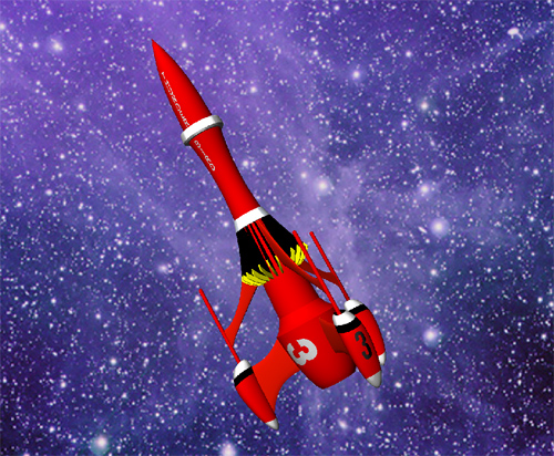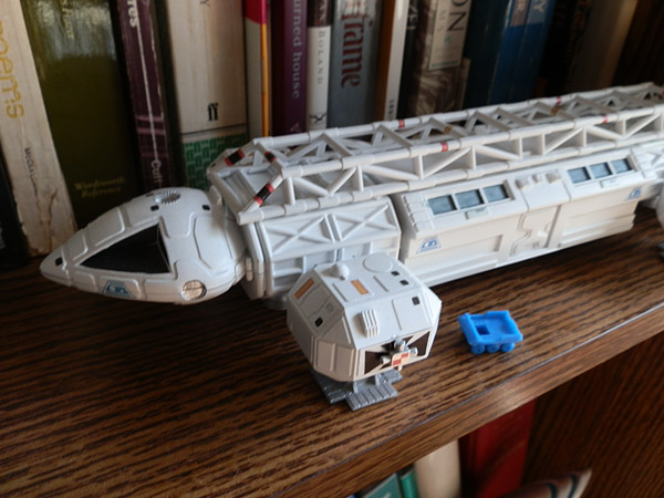
I’m a big fan of Blake’s 7, as is a friend of mine. He asked if I could print a Liberator, the space ship the rebel band discover and inhabit, and I said “Already downloaded, man!” Thingiverse has a Liberator that looks to print rather nicely. It is not terribly detailed, but if this print is successful, I may add detail later and reprint. Originally it was modeled to print at about 19″. I’m going to print it at half-scale and see what I get. Later, I may do the full 19″ model.

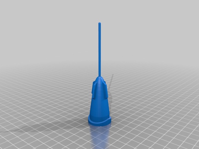
This post will be updated as I go, rather than start a new post. This is tonight’s effort: (July 2, 2013). I took the Fuselage Front Spike and am printing it twice at .5 scale, at .2mm, Normal.
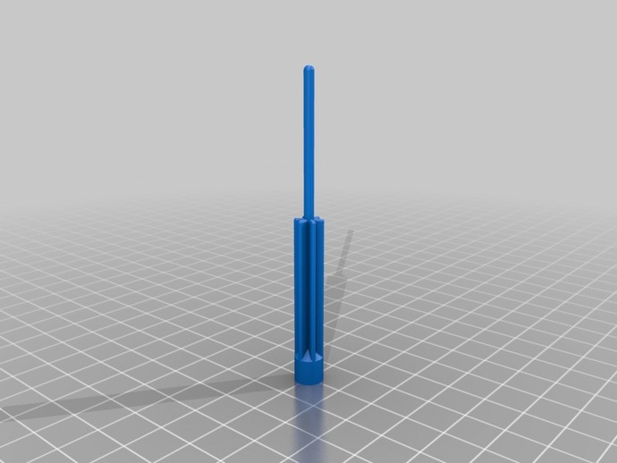
I tried this part first because it has a thin spike. This may not print well, and if not, I will have to load the model into Maya and scale the spikes outward so they thicken. But until I print this test, I won’t know that. Here is the printing record:
Fuselage Front Spike
281 layers – These numbers will represent a PAIR of parts, for making TWO Liberators.
3.2 grams of ABS
22 minutes
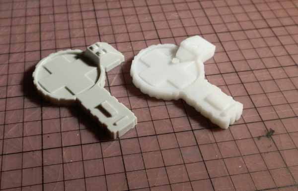
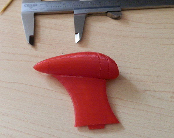
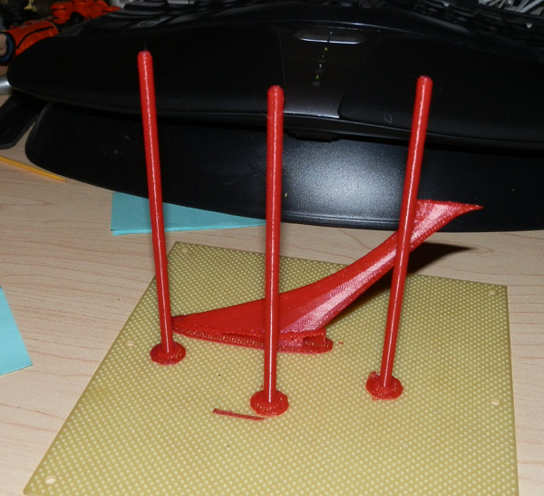
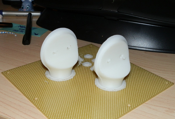
Ok, color me impressed. Here is the pair of Front Nacelle parts hot off the printer. It printed the spikes! (Close-up they are a bit rough, but it printed them!)
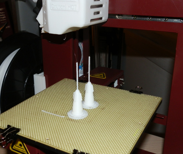
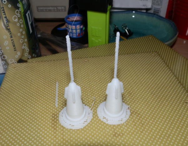
You can see the struts are a bit rough. Not unexpected. I’m a bit surprised they came out this good. I may later model holes in the pieces and use some other material for the thin struts, since there are four of them on the model, and they will be quite delicate. I think I may try to find some metal wire to replace them. It will require re-printing these pieces, but that’s not painful.
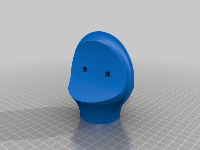
Fuselage Front

291 layers
20.1 grams of ABS
1 hour, 41 minutes
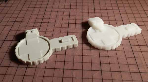
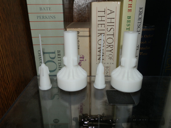
And here it is (two copies) next to the Front Nacelle:
Fuselage Main
210 layers
15.9 grams of ABS
1 hour, 25 minutes
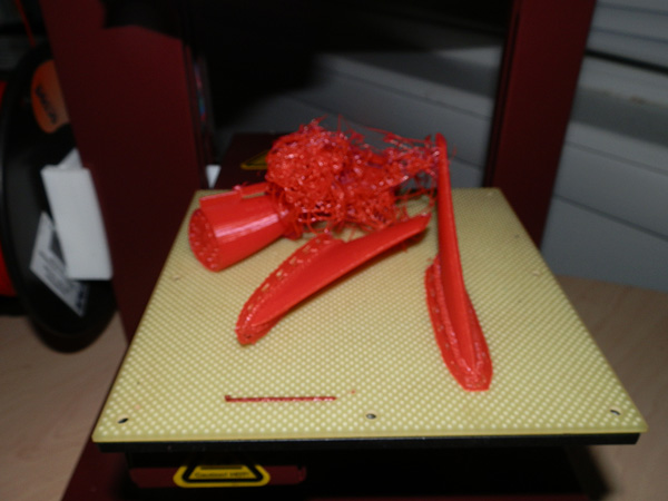
You may notice fine spiderweb-like hairs stretching between the two pieces. This would be bad if it was on the actual piece itself, but it isn’t. The vertical lines you see in front and on the sides are support scaffolding for the holes that are in the side of the fuselage. Since those holes are horizontal, there needed to be some support material to support the roof of those holes. Think of the roof of a cave. So those support scaffolds print very quickly since they are so tiny, and the print nozzle goes between them very quickly, forming these hairs. It does not do it between regularly printed parts, usually (an exception for cheaper filaments melting at too hot a temperature.)
But those vertical scaffolds just tear away to form clean clyinders.
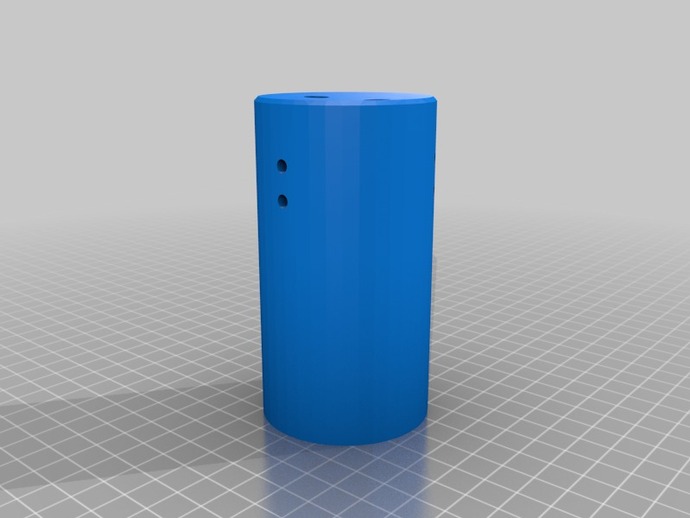
How stupid! I realize as I test-fit these together, that these Main Fuselage pieces must have been printed at .4 scale, not .5. I must have fat-fingered the scale value. They are too small! Have to re-print!
So I reprinted them in what must be the most boring print ever – Two vertical, unfeatured cylinders, 2 hours, 41 minutes. Zzzzz. :-)
Next up (tonight):
Fuselage Rear
278 layers
27.5 grams of ABS
2 hours, 12 minutes
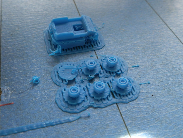
I decided since I needed so many of the pins used to connect the pieces, I’d print six of them with these two rear fuselage parts. However, one pin fell over and it caused some downstream printer errors. Here is the result: (I have already removed the pins from the board.)
See the hairs coming out of the one on the left? That’s where the print head tried to print a sixth pin, finding nothing, it left filament on the air, trailing it to this piece. A little X-Acto knife work and you would never notice.
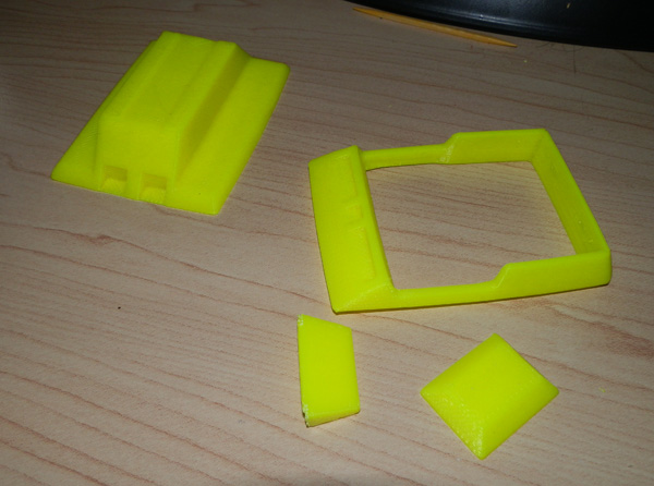
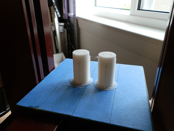
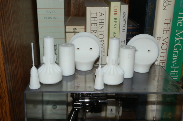
Here are the parts as they are now:
Nacelle Front and Nacelle Spikes
Printed two each of these last night. As expected, the spikes came out about the same as the front spike. But it does highlight the need to remake these thicker for a smaller print, probably with holes so I can fit in toothpicks or something else. 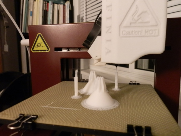
Nacelle Middle
206 layers
27.0 grams
1 hour, 41 minutes
These printed without issue.
Nacelle Strut

166 layers
2.8 grams
21 minutes
I printed six, so triple the time and grams above. I wanted them done so I printed them all. It highlighted some issues: Where the pegs have holes, the scaling down thinned the walls so much that the holes showed through the printed walls, leaving gaps. Not sure how that plays out when assembling them. We’ll see later.
Here’s what I have done now:
But I had a problem. I was getting ready to print something else in a new color when the nozzle head jammed. I withdrew the premium natural color you see here, and extruded in a yellow. I’ve done this dozens of times without issue. However this time the extrusion didn’t work. It pulled the filament into the head, but then the feeder motor began a clicking noise, like it couldn’t advance the filament. I withdrew it again and checked the manual.
It’s vague on what to do in this situation. It does give instructions on how to remove the nozzle if it’s clogged, but I removed it and tried to extrude again, but it still got stuck. So the problem is in the feeder, not the nozzle, even though the nozzle could use a cleaning.
I sent an e-mail off to Afinia, but this being July 4th, no one will answer it today. There goes my evening of printing stuff.
Oh well… so for now:
THE PRINT SHOP IS CLOSED.
Afinia got back to me on Monday, today, after a four-day weekend, with a PDF file showing exactly how to unclog the feeder mechanism. Not wanting to void the warranty, I certainly did not poke around with this machine on the weekend. But when I got home this evening, I took the head off, took it apart and fixed it.
For the second time, Afinia has fixed my printer by e-mail.
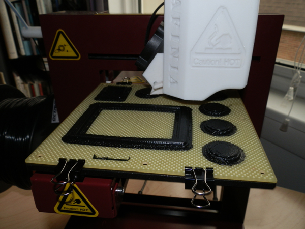
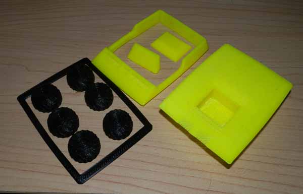
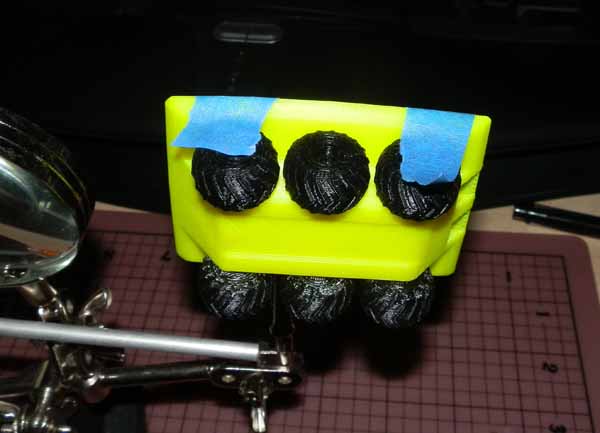
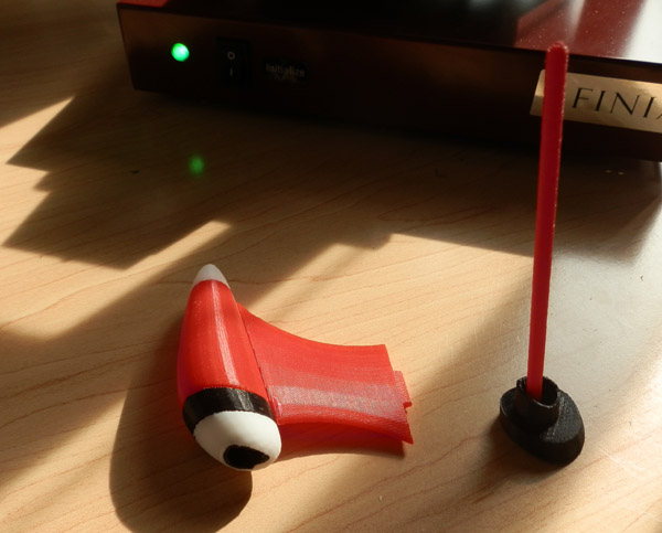
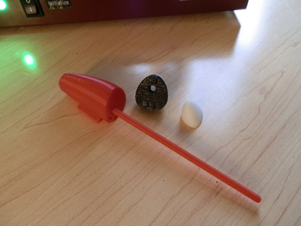
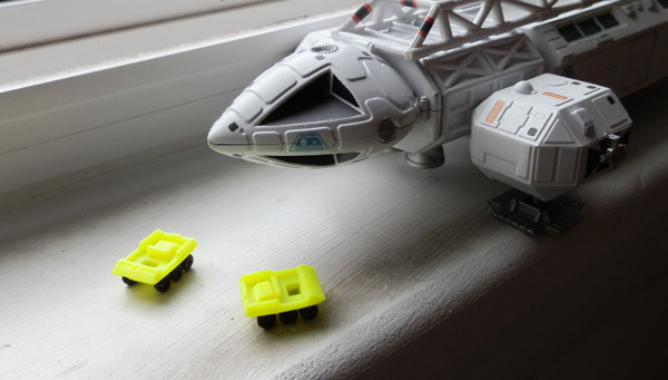
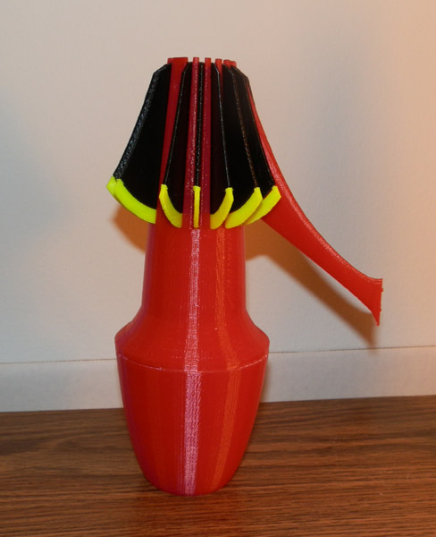
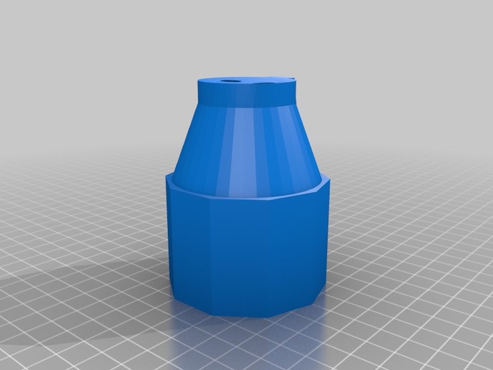
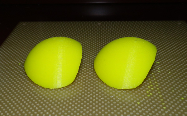
So tonight I continued printing Lierator parts. I wondered what color to print the “green globes” in, since I had no green. I was thinking blue, but the ugly neon yellow I had seemed to have an internal glow about it, so I went with that for now. When I get green, I’ll reprint these and replace them.
So tonight I printed four of these, two for each copy of the Liberator I’m making:
Globes:
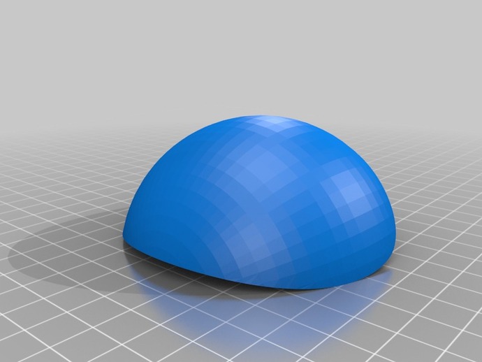
127 layers
14.5 grams
1 hour, 38 minutes
This is the end result. I printed these twice, so I have all I need.
July 10 Update
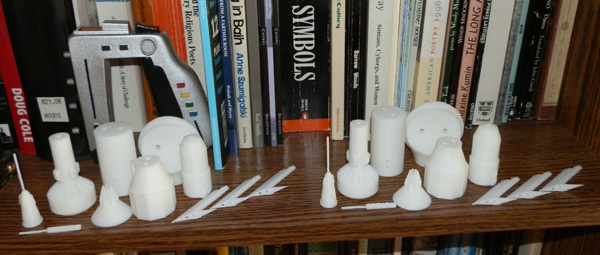
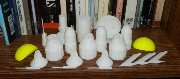
I printed four Nacelle Spikes and two Nacelle Middles last night. This morning I printed two Nacelle Rears. This completes one model, leaving only two more Middles and Rears to print for the second model, which I will print tonight.
All that will then be left is the pegs to connect all the bits together, and the display stands. I’ll start on that as soon as possible.
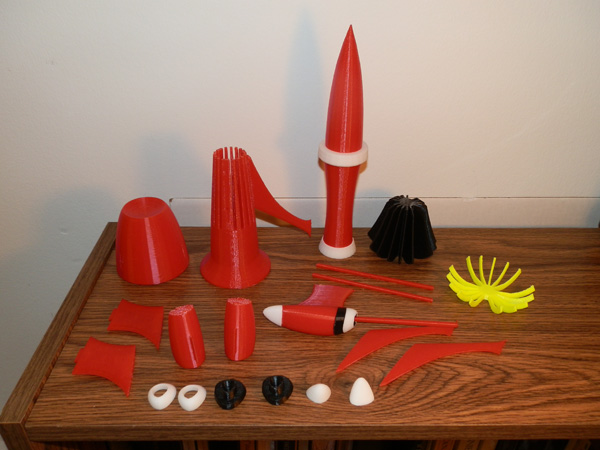
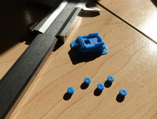
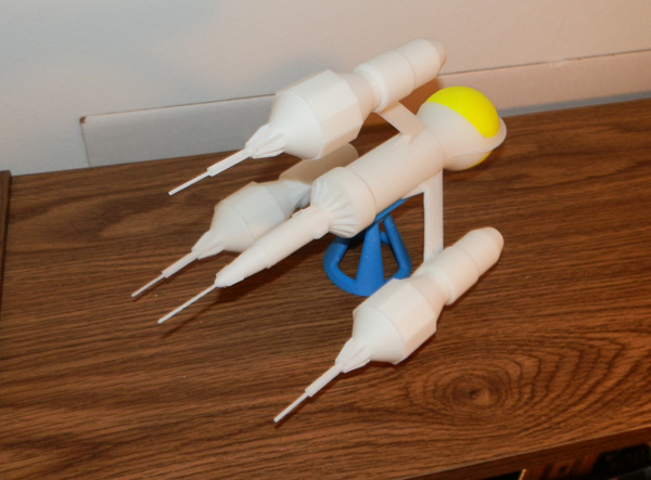
Until then, here’s a photo of all the parts (minus the pegs and stand):
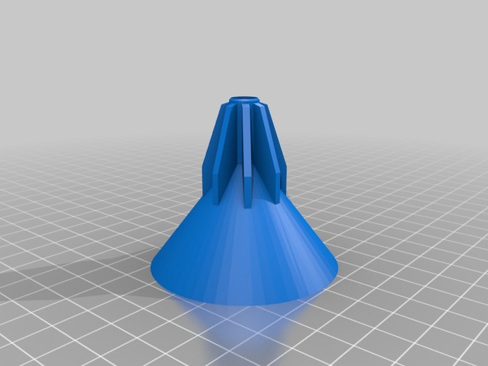
So with all the parts printed, including all the pins I need (and the small ones are small!) I printed the display stand:
Display Stand:
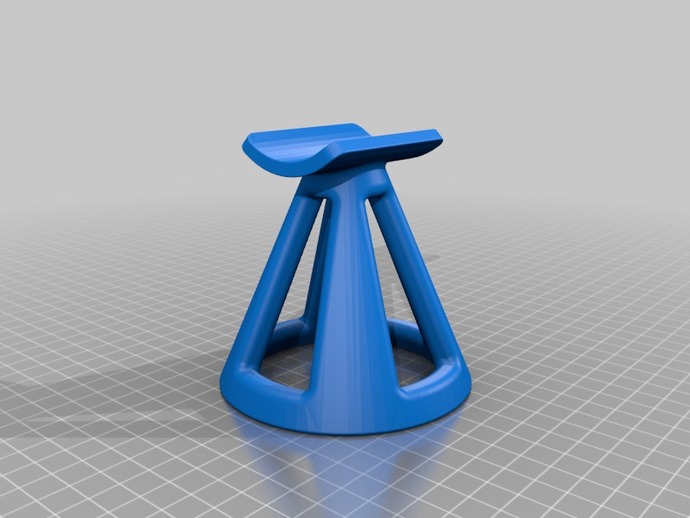
239 layers
13.0 grams
1 hour, 11 minutes
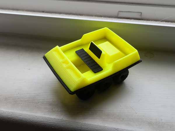
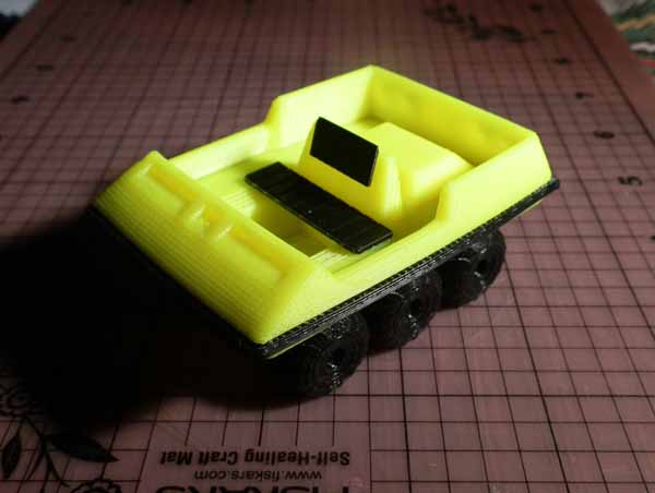
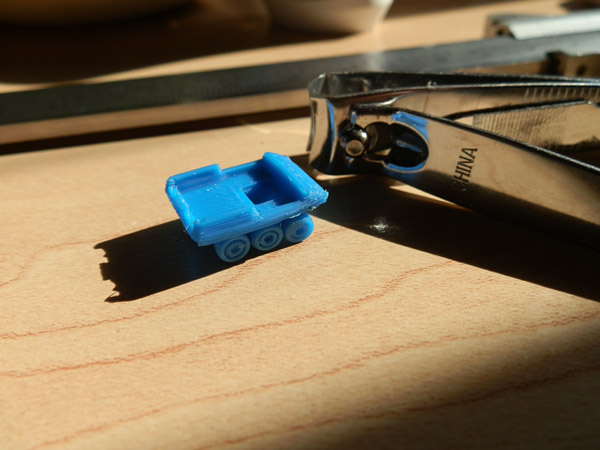
So with this done I used clear binary epoxy resin to glue it all together, which was a bit more of a challenge than anticipated due to the pin size. I had to use a metal tool to widen some of the holes a bit, and clip some of the pins. And when gluing one engine onto the body the pair of pins just broke, so I just had to hold it, hoping the alignment wasn’t too bad, until the epoxy hardened. It’s ok, but it’s off by a degree.
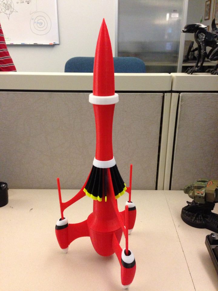
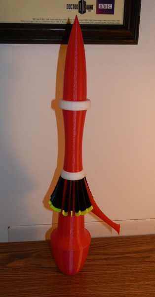
Here’s the first final completed Liberator.
And now for a tally for two models:
Total ABS Used – 263.8 grams
Total Time – ~25 hours, including the pins
The Afinia White filament costs $45.00 for 700 grams (plus shipping, but let’s leave shipping out of this for the exercise.)
$16.96 to print a pair of these. Not at all bad.