SP’LUNK! A 3D Printed Tabletop Board Game

SPeLUNK Logo
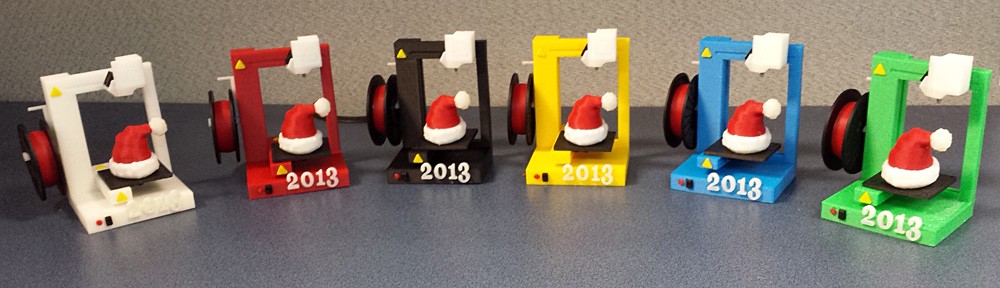
For a while now I have been wanting to create a board game and use my 3D printer to create the pieces, at least for player markers, but ideally, an entirely 3D printed game.

And for a long time I have been fascinated with hex-grid games. I knew I wanted my concept to work on a hex grid. Better, I chopped each hexagon up into triangles, so it’s actually a triangle game played on hexagonal game board sections.

I wanted to use the idea of building a pathway on the board, and immediately I thought of the old Text Adventure “The Colossal Cave”. I began drawing out sketches for board pieces and what features the game would have.

This was my preliminary sketch:

splunk-pieces-sketch-02

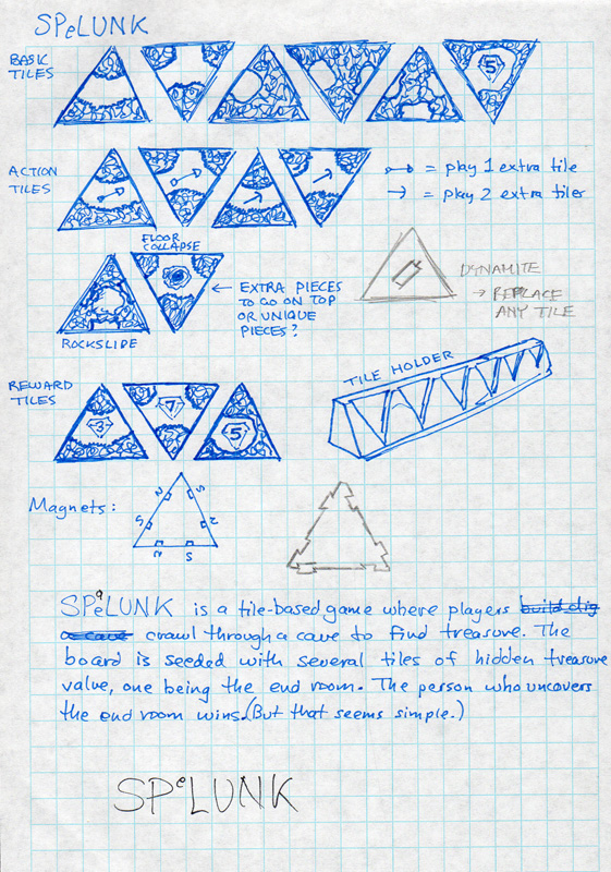
This one sketch covers a lot of ground. It not only describes the basic premise for the game near the bottom, it creates the game name and logo as well, and even discusses a couple of ways to create the pieces.

As for the pieces themselves, they show a fairly detailed set of pieces, most of which actually ended up in the game, or at least in some form.

I wanted the pieces to be triangular, and they needed to link together on a table to form a path, and could get quite dense. I thought I’d use micro magnets (I have a lot of those) but it would require six magnets per piece. Then I thought of puzzle piecing them together. Not terribly practical.

Then it hit me. I have a Deluxe Scrabble game. The board is not like the folding cardboard board from the standard edition that so many people are familiar with. It has ridges on the grid leaving each piece recessed so when you lay a piece, it does not move:
scrabble-deluxe-01

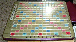
Perfect. I would print board pieces with ridges to keep the pieces in place. And since I couldn’t print the whole board as one part, I actually was forced to create a board that was more flexible than I had even intended originally.

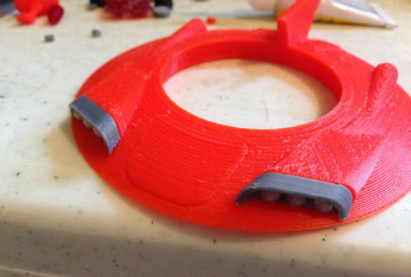
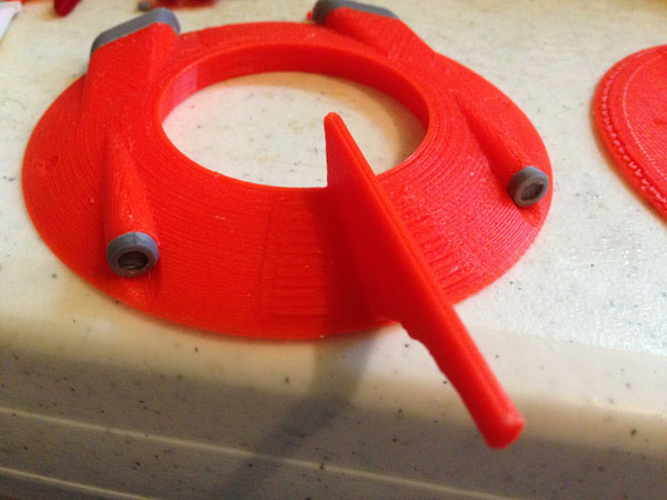
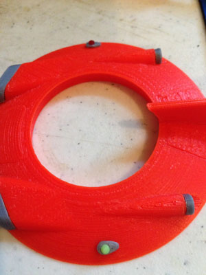
I would create hexagons with 24 triangles in each piece. Each piece would then be connectable to each other by a puzzle system. Underneath each one is a butterfly shaped recess. I printed butterfly-shaped connectors so any board piece can connect to any other.

splunk-board-sections-01

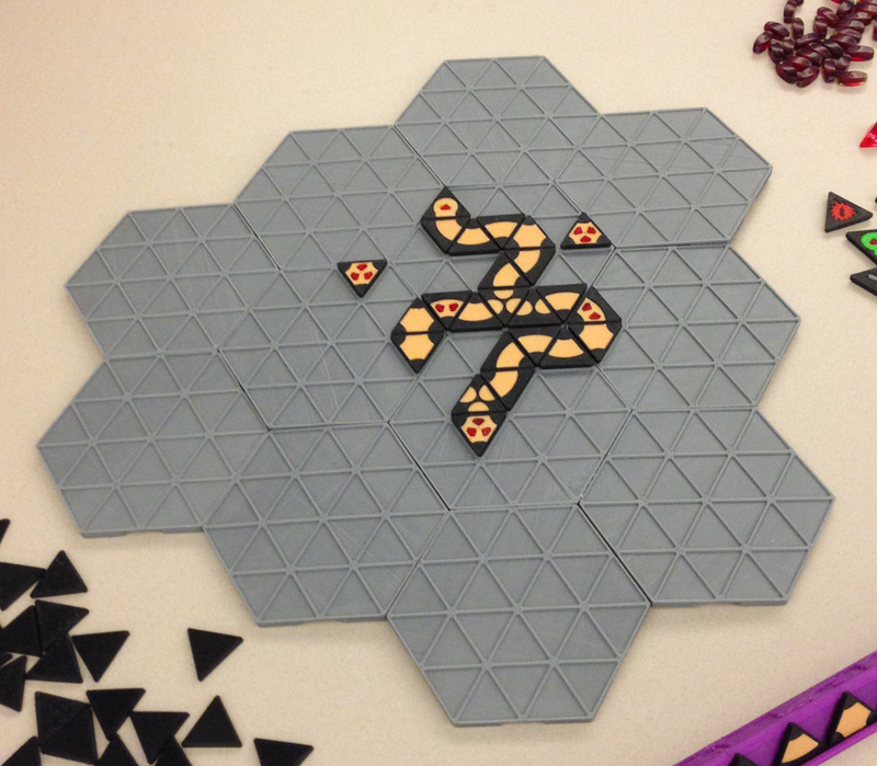
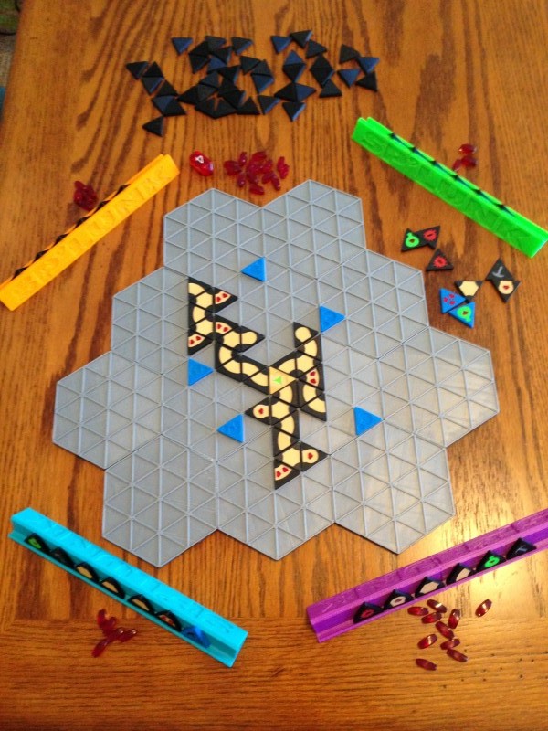
Here I show 12 sections connected into a triangle shape. But the great thing is the players can decide on their own exactly what board layout they want to play on.

You can also see by this picture that the pieces are 3D printed in two colors (or more) and include tunnel pieces that connect two of the sides of each triangle, or 3, and some block the tunnels. (I later determined through playtesting that the blocking pieces had no actual effect, so I eliminated them.)

Some pieces, you will note, have gems (red inserts) that are scoring pieces. Note also the red crystals at the top right of that picture. Those are the scoring markers, and when the game is over, the player with most of those gems wins.

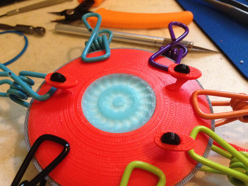
I printed piece holders much like Scrabble holders too, in several colors. Those had to be puzzle-piece connected because my printer could not print them in one run.

Before culling some of the pieces and changing things around due to playtesting, this is a photo of the pieces used in a single game:

splunk-pieces-01

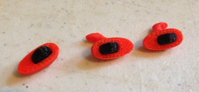
I also printed instructions with illustrations. The pieces I ended up with are, with a total count of each:

Tile Count_v2

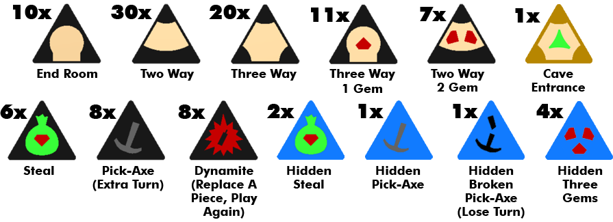
Arbitrarily, also, players can add more pieces (my game will include extras) so they can customize gameplay at will.

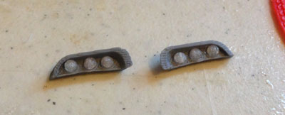
Above, you see the tunnel pieces, then tunnel pieces with gems (for scoring). Then the Cave Entrance which is the first piece layed in gameplay, and all tunnels lead off from this piece. Then we have the Steal piece (green bag with gem) which allows a player to roll a D4 die and steal that number of gems from any player (or players). The Pick-Axe gives a person an extra turn. Dynamite allows a player to remove an existing board piece and replace it with one of his own, and then play any second piece he’d like.

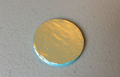
The four different blue gems are placed on the board in turn before gameplay by the players, upside down (there is a ? on the back) so no player knows what they are.

During play, you build tunnels on the board with the aim of reaching the 8 blue pieces. When you reach one you reap the reward or pay the piper. Most of the pieces are beneficial, gems, free turns, steals, but one loses you a turn.

Here is a recent shot of the game I took for the back of the box:

IMG_4191

I have been playtesting it and a lot of the changes that came since the first design are thanks to some excellent suggestions by playtesters which have helped the game immensely.

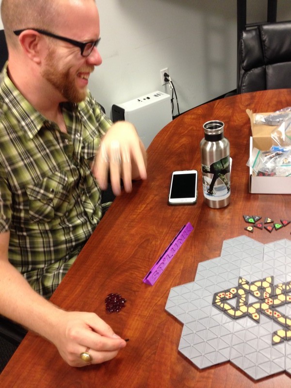
Here my friend Matt enjoys (or pretends to enjoy?) a playthrough of SP’LUNK.

IMG_4021

I also created a box out of an Afinia filament box, and create labels for it. Here is the cover:

Box_Cover_Art_002 copy

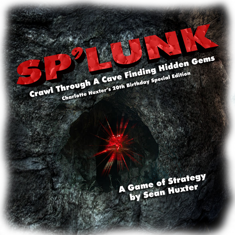
This version has a special sub-title, as it was a gift for my daughter on her 20th birthday. Her friends have played SP’LUNK and they seemed to like it so I gave her a copy, hoping they would play and perhaps suggest even more excellent alterations.


Warping Prints And How Not To

One of the issues I’ve had with the printing of ABS plastic from the beginning is warping. The print bed is heated and it results in warped prints that often are useless.

I created a nice case for a ZoomFloppy circuit board:

zf-done

Looks ok, doesn’t it? Well it isn’t. Not really. This was intended to be printed top-side-up for the top part, and bottom-side-up for the bottom half, giving the exterior the best surface. But when I printed it that way, the seam that joins the two “halves” warped and would not fit together.

To fix this I printed both parts face down, which is not ideal, since the underside of any print with my printer doesn’t print as finished as the top side. So for this case, the interior actually looks more finished than the exterior.

The first thing you need to know about printing in ABS plastic is that there are several useful methods to hold down prints, but even they don’t work perfectly all the time.

Acetone Slurry

This is a common method. Take some acetone in a glass jar, and mix in snippets of ABS plastic (10/1 ratio by weight) and let the acetone dissolve the ABS until you have a milky slurry.

Use a brush (non plastic) and brush a thin layer onto boroscilicate glass (which I use for my print bed), let it dry (seconds) and print on it.

Then magic happens. The print holds down almost all the time, then when it cools (after it is done) you can hear the plastic releasing itself from the glass in little cracks. When the glass is cool the print comes off easily.

But even this fails me.

I have been reading up on many different methods to hold down prints, and one was purple Elmer’s Glue Stick. I hadn’t tried it mostly because from reading early articles, it was apparent that this method wasn’t quite as good as the acetone slurry.

But this past week I read more, and people are swearing by this method as one of the best, and certainly it’s neater to maintain, so I decided to give it a shot.

This weekend I bought a purple Elmer’s Glue Stick and cleaned off my glass sheets and gave it a try.

All I can say is WOW.

Yes, I had a couple of warped prints, but that may have been inexperience.

Mostly, the prints held down like crazy and as the glass cools you can hear a loud POP as the print releases itself from the glass. Sometimes a small print may actually fly into the air a bit and fall off the glass. It’s wild.

So for those of you who are printing in ABS with a heated print bed (PLA does not require a heated print bed and is less prone to warping) and you haven’t tried this yet, run, don’t walk, out to the store and get one of these glue sticks.

elmers-purple-glue-stick

JANI-TOR Updated

Twice now, my JANI-TOR 3D printed robot model has broken. Once I dropped it while carrying it, and once it toppled over seemingly on his own on my bureau. Perhaps he’s a bit front heavy.

This second time, the head came clean off, so I took this opportunity to redo the head.

The original head disappointed me because the whole point of this model is JANI-TOR is contemplating a ball. But my original model was not looking at the ball, he was looking far too up and forward:

jani-tor-02

So I took the opportunity to make an alternate head that is looking towards the ball. Here you see his new head attached, and his old one detached:

jani-tor-heads

There. Fixed it.

Rocket Display Stands

Some time ago I created a rather nice Thinderbird 1 and a Thunderbird 3 ship from the new Thunderbirds Are Go! tv series.

Originally TB3 had no display stand, since it could stand on its own, while I created a stand for TB1 that was just a four leg Sci Fi thing:

This TB3 stands about 18″:IMG_4035.JPG

This TB1 stands about 14″ tall:IMG_4213.JPG

Recently I created new stands for these, and for my smaller TB1 and this weekend, for my newly-arrived toy Thunderbird 3 made by Vivid Imaginations.

This is my larger TB1, 14″ without stand, 18″ with:IMG_4121.JPG

This is Thunderbird 3, 18″ without stand, 22″ with:tb3-display-stand-01

This is my smaller TB1, standing 7″ tall without stand, 10″ with:tb1-small-display-stand-01

And this is the new Vivid Imaginations Thunderbird 3 (nicely done, guys, it’s really a nice toy!). It stands 7″ without stand, 11″ with:vivid-tb3-display-stand-01

Re-Introducing JANI-TOR

bjanitor

In the late 1990s I created a robot in Lightwave, and called him JANI-TOR. The idea was that he was a menial sanitation robot sweeping the floor of a lab he’s not necessarily supposed to be in. His broom bumps a ball (a familiar one to Canadian children in the 1970s, and is NOT, I repeat, NOT the PEPSI logo!) and follows the ball to where it rolls to a halt under a huge Van de Graaf generator, where he reaches down to pick it up as the sparks get increasingly closer to him, and then he stands up, the generator waning, and examines the ball, tosses it in the air where a huge spark disintegrates it, turning it into dust. Undaunted by any of this, JANI-TOR continues about his business.

I put the video together but never did the sound.

This week I decided I wanted to 3D print him. Actually, I decided this many years ago when 3D printing became possible.

This week I remodeled him (can’t find the original Lightwave files), updated a few things, like his hands, and beefed up his feet, and printed him in his broom-carrying, ball-surveying pose.

Here is a tray filled with all of the parts: The dark teal of the original was not available, so I used a lighter version, and I still think he turned out well:

jani-tor-parts-01

And here he is, printed out. As you can see by the parts, it’s all tab and slot connections, and so he’s not articulated. He’s a statue. But a nice one.

jani-tor-01 jani-tor-02

jani-tor-03

I posed his eyes looking a bit too high. I can fix that by printing a new head for a different version.

Note the broom. I could have 3D printed that too, but guess what? Sometimes 3D printing is not the only, and not necessarily ideal, method to make something. This time I used two paint brushes (one for the wooden base, and one for the bristles) and a piece of wooden dowel. The hand has a cylindrical space in it so the broom can slide into place easily.

Here are the movies, one is a walk test, and the other the full video. These are tiny because it was the late 1990s and this size took long enough to render. It was also a test only.

Here is a series of single frames from the animation. Each one mimics the storyboard frame I created for them very closely. I stuck to my storyboard fairly strictly.

shota shotb shotc shote shotf shotg shoti1 shoti2 shoti3 shoth1 shoth2 shotj shotk shotl1 shotl2 shotl3 shotm1 shotm2shotm3 shotn1  shotn2 shoto1 shoto2 shoto3


Rick & Morty – Flying Saucer Car – Talk about Iterative Design

IMG_4093

I am involved in many projects, both at home and at work. Each one has shown me how important iterative development is. I have found that nothing is ever “done” but it does get ever-closer-to-done.

At the request of a friend I took on the fun task of modeling and 3D printing Rick’s flying saucer car from Rick & Morty, the Adult Swim cartoon series.  This request was probably prompted because I had been creating things using vending machine bubble capsules, and the ship has a perfect bubble-capsule canopy. (This is a good series, but it is not for kids.)

I found first that no matter how much research I do on the web, I see no two versions of the ship are alike, which is expected because they are hand drawn by various artists.

I did a quick version that worked fairly well:

rm-test-print-01

But of course this was a test print only. I had full plans to do a detailed interior.

The problem: I made the aperture for the capsule tight. Very tight. Applying the capsule should be done only once, and it could be tight. To get it to fit, I had to warp the edge inward, snap most of it in, then let it relax outward to fit the rest of the circular indentation.

So that worked. Then I added the detailed cockpit interior. When I was done, I had 50 individual pieces to make the car with the detail I wanted. (Some of this was to make printing easier or cleaner, such as making the interior tank out of 3 pieces instead of 1.)

rm-full1-04 rm-full1-03 rm-full1-02 rm-full1-01

Uh-oh. I soon found that there was no room to bend the capsule inward to fit it properly without dislodging or breaking items inside the cockpit.

I had to think for a bit. This version is solid. Can’t fix it. So perhaps I can try to get it to fit after all, but it will be hard.

But then I came up with the perfect idea:

I would break the interior out as a circular floor, and cut it out of the body, and then install it from below after the bubble capsule is in place. The bottom would glue to the body, and then the oval under-piece will cover the hole. The result will be visually identical, but far easier to assemble.

UPDATE: Nov 23, 2015 – The Finished Ship

Here is a photo of the finished ship. I also created and added waterslide decals of the “bumper stickers” on the side of the ship.

rm-ship-finished-decals-01

This version has the separate cockpit which allows for easier assembly.

Sooooo… interesting story:

This whole project was suggested to me by my friend Bil Mauritzen. When I sent him a copy, he showed photos of it to the co-creator of “Rick & Morty”, Justin Roiland who reportedly said it was the best bleeping thing he’d seen.

I sent a second one to Bil, who will be giving it to Justin.

So that happened.


3D PRINTED ZOETROPE – My Grand Project

What Is A 3D Printed Zoetrope?

Here’s one I found on YouTube that I like:

Ever since I saw my first 3D printed Zoetrope (a spinning disk with 3D printed figures on it, spun to a synchronized light which simulates a smooth animation) I set out plans to make one myself

The basis is easy – 3D print a group of figures, each frozen in a single frame of a looping animation, stuck to a spinning wheel and a strobe light set to synchronize to the rotation until you see a perfect animation.

However, there are complications, the largest being how to synchronize the light so it always aligns to the figures on the disk at an exact angle. You can spin it at a variable rate with a potentiometer on the motor and then use a variable strobe and hand-sync the two until they work, or fall out of sync due to variations in current, etc… but what I really wanted is an absolute sync, and I think I figured out a good method:


The Arduino

ArduinoMicroFront_450px

I intend to use an Arduino Micro to synchronize the light to the spinning disk. This should be easy, but some experimentation has to happen first.

First, I purchased several infra-red light emitter/detector pairs. These are LEDs, one of which emits an infra-red light, and the other detects that light. Using the pair, I should be able to trigger a circuit whenever the light is detected (or not detected) by the detector.

There are numerous examples of how to do this on the web, but it’s fairly easy. Simply hook up the emitter to an Arduino output (with an appropriate resistor to ramp down the voltage so as not to blow the LED) and the detector to an Arduino input.

Next, I will write a simple piece of Arduino code that registers the input strength (the detector is analog, so it can detect any amount of light the emitter emits.) I will use that with a variable threshold to trigger another output that I have hooked up to a very bright LED light (and perhaps even to the switch of a third-party LED flashlight).

This way I can light the LED whenever the detector sees the emitted Infrared light.

I can trigger the light to turn on and stay on only for a very short time.


Synchronization

To synchronize, I intend to print a small hole (or tab) near each 3D printed figure “frame” and then, no matter how fast I spin the disk, it will itself trigger the Emitter/Detector to flash the LED flashlight. So I should be able to spin an unmotored disk and have it sync, and as it naturally slows down, the sync will remain solid.

But of course I will use a motor to keep it going, and hopefully a motor which speed I can adjust, so I can speed up and slow down the animation.


UFO 04 – Jetson Cruiser

The Jetson Cruiser

This is my latest UFO print:

ufo-04-cruiser-08

Admittedly, I grabbed the idea from this wonderful model I saw on the web:

IMG_3852

I did make my own alterations and adjustments, though.

What I was aiming for was something out of the Jetsons, a flying saucer that invoked a 1950s car feel with fins and chrome lights. I have no chrome, so I was stuck with a gray filament that is called silver but is not.

Here are all of the parts that make up the Jetson Cruiser:

ufo-04-cruiser-parts-01

Assembly

Gluing the bumper to the bottom half:ufo-04-cruiser-assembly-bumper-01

Here the cockpit assembly (console, pilot seat and comfy couch for five passengers) is attached to the bottom of the saucer:ufo-04-cruiser-assembly-cockpit-01

Then the semi-spherical bubble capsule cap is put in place. The fit is so perfect I don’t need to glue it:ufo-04-cruiser-assembly-cockpit-02

Then I blue the six clear translucent lights to the light covers:ufo-04-cruiser-assembly-headlights-01

And I attach those to the body:ufo-04-cruiser-assembly-headlights-02

The tail-light rims go on next:ufo-04-cruiser-assembly-tail-lights-01

Followed by the customary navigational lights, green on the left, red on the right:   ufo-04-cruiser-assembly-running-lights-01

And then the actual tail lights:ufo-04-cruiser-assembly-tail-lights-02

I glue tires into the three wheel housings. Note: These wheels are printed in a flexible black, so they feel like rubber and have some bounce. In a future version I may add axles and allow them to roll:
ufo-04-cruiser-assembly-wheels-01

Inserting the vertical thruster. The thruster is printed in a translucent glow-in-the-dark icy blue. So when it’s glued to the underneath, it shows the orange (and gray from the cockpit) through. To avoid this, I attached a circle of tin foil to reflect light back out:ufo-04-cruiser-assembly-tin-foil-01

Then I glue the thruster in place underneath, and attach the wheels:ufo-04-cruiser-assembly-bottom-01

Now the two halves get joined, for a completed model:ufo-04-cruiser-assembly-main-body-01

The Showroom

ufo-04-cruiser-01 ufo-04-cruiser-03 ufo-04-cruiser-04 ufo-04-cruiser-06 ufo-04-cruiser-07 ufo-04-cruiser-02

ufo-04-cruiser-09


Cute Prototype

When I prototype, I use colors I normally have a lot of, but don’t use a lot of, like purple, pink, neon yellow, etc. In the first print of this model, I used purple and pink with green and white.

It was intended only for fit and to determine what issues the model would have.

But my daughter loved the color scheme and basically demanded it, so it’s now hers. Here it is.

12516134_10153175455856105_787960785_n

New Rocket – Apollo 42

apollo-42-complete-engines-extended-03A couple of years ago I bought a Pegasus Hobbies model kit called “Apollo 27” because it looked awesome. I haven’t built it yet, but I will get to it.  It has these four rocket engines offset from the body with a solid structure holding them in place. I looked at it and thought “Hey, what if they swung in and out?”

apollo-27-box

Apollo 42 is born. (42 – Reference to the Ultimate Answer.)

I changed the design naturally, but I liked the original enough to keep the basic shape.

Here are the parts: One engine has been assembled to show how the parts fit together.

IMG_3896

A bit about the design:

Like many of my rockets, it prints in multiple colors. I design it so that body stripes are individual cylindrical pieces, and I use holes and pegs to align them for gluing (the black mass in the picture is a group of pegs.)

Each hinge arm has a hole in either end. In the body of the rocket and in each engine, there are four hemispherical bumps that the hinge arms get pushed onto. Once in place, this acts as a very solid hinge. In a future design I may change how this works, but for this one it works well. A careful eye can detect that at each end of the hinge arms there is a funneled channel carved in to make sliding these onto the bumps a bit easier (though it’s no easy task.) Once snapped on, however, they work very well.

The number 42 is inlaid using four individually printed numbers, booleaned into the body and angled correctly. I do this by making the letters, the making a cutting tool object that is just a bit larger all around, so the number can slip into the cavity without too much difficulty.

I designed the rocket with two hinged arms for each rocket engine. Each engine retracts to a recessed section of the main body, and extends outward to a maximum distance.

As it is now, each engine can be pulled in and out individually, and because each uses two hinged arms, the angle stays correct as you extend them and retract them.

apollo-42-complete-engines-retracted-03 apollo-42-complete-engines-retracted-04 apollo-42-complete-engines-retracted-01 apollo-42-complete-one-engine-extended-01 apollo-42-complete-two-engines-extended-01 apollo-42-complete-three-engines-extended-01 apollo-42-complete-engines-extended-01 apollo-42-complete-engines-extended-02


I will note that during assembly I came up with a great way of making it so that when you pull out one engine, the other three will also pull out, and in. I will be working on that in the future, perhaps Version 2.0 of Apollo 42.