Thunderbird 4 – A 3D Print

tb41

I have been looking for good models of the Thunderbird rescue craft that I did not want to bother to model. Thunderbird 1 and 3 were ones I wanted to model, and thought I could do a good job. However, the curves and nuances of TB2 and TB4 made me not want to go through the trouble. TB5 I could do easily, but I’m not sure I want to.

So recently I found a model of Thunderbird 4 on Thingiverse. But it had some issues.

First, it was solid. I wanted it to be printed in colors. Also, various bits were just thin polygons placed in the mesh, not combined and not closed.

I remodeled those bits, then split the body in half, adding detail, and 3 screw holes to fasten the two body halves together.

All parts

Yellow: Front, rear, engine hoods, fin, nose, lightbar arm.
Red: Stripes and engine housings
Silver: Grill engine inserts
Blue: Windshield and dome
Clear: Lights – raw filament
tb4-parts-all

Adding red engine housing stripes and grills:tb4-grills

Attaching front and rear with 3 screws:tb4-body

The screws:
tb4-screws

Nose stripe:
tb4-nose-stripe

Nose:
tb4-nose

Engines:
tb4-engine-housings

Attaching engines:
tb4-rear

Adding fin:
tb4-fin

Adding light bar:
tb4-lightbar

Windshield and dome:
tb4-windows

Clipped filament strands to fit the light fixtures: (Fuzzy picture, sorry.)
tb4-lights

Result is rather nice, even though I had to work hard to get the flat bases (where the body halves meet) to print flat. My printer has been warping up things with large flat surface areas. But it’s not a bad model.

tb4-finished

The More Printers The Merrier

This is a short video (no sound, sorry… my iPhone’s front microphone does NOT work when shooting video) showing my new H480 printer (left) working at the same time as my H479 (right).

It is currently printing two halves of a case designed to house a circuit board called ZoomFloppy which allows PCs to read and write to Commodore 64 disk drives.


Thunderbird 1 – Take 2

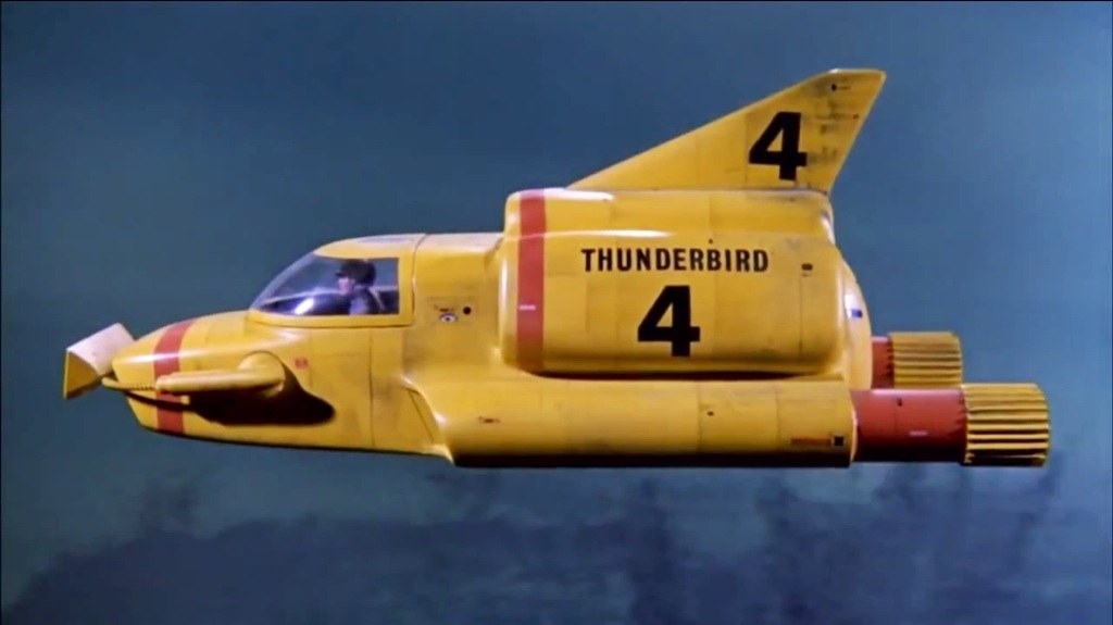
Last year it was announced that WETA, who made all of the awesome designs for the Lord of the Rings and Hobbit movies, among other accomplishments, would be reviving the iconic TV series Thunderbirds, created by Gerry and Sylvia Anderson in 1964. The new series is going to be named after the first of two feature films the couple also made back in the day: Thunderbirds Are Go.

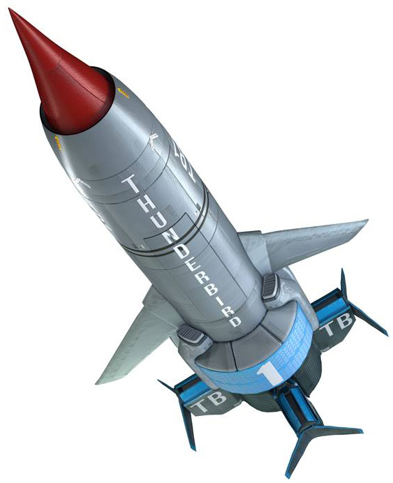
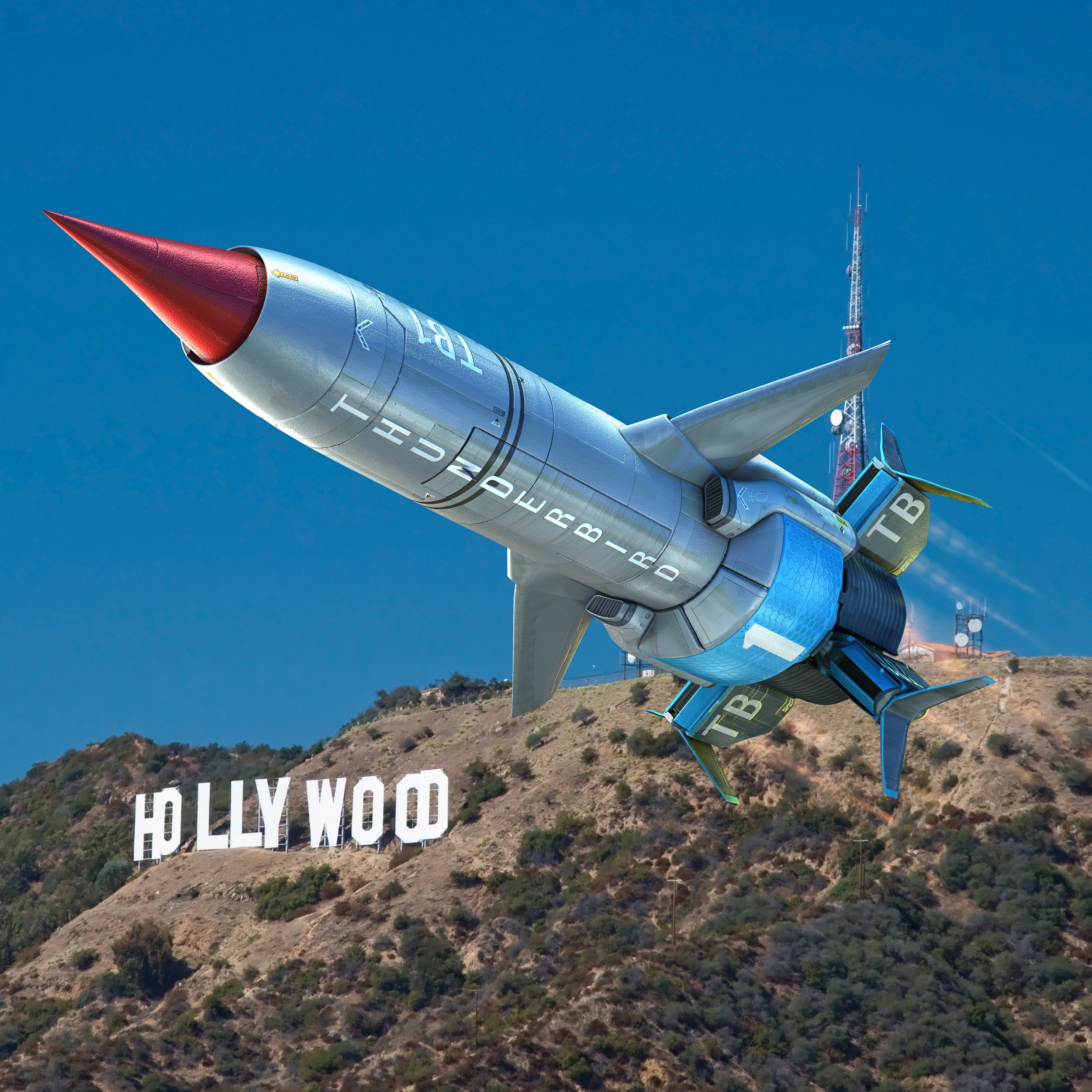
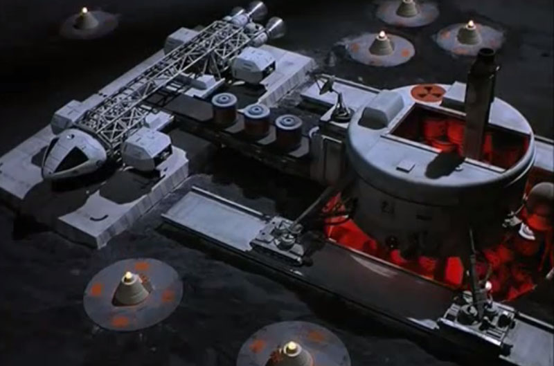
The first big teaser image from the show is the CGI model of the updated Thunderbird 1, seen here:

tag-tb1-cgi-model-01

It was soon followed by this image, almost the same, of Thunderbird 1 (TB1) flying inverted over the Hollywood sign:

tag-tb1-cgi-model-02

So I set out to model this and 3D print it using my Afinia H479 printer. (And my Afinia H480.)

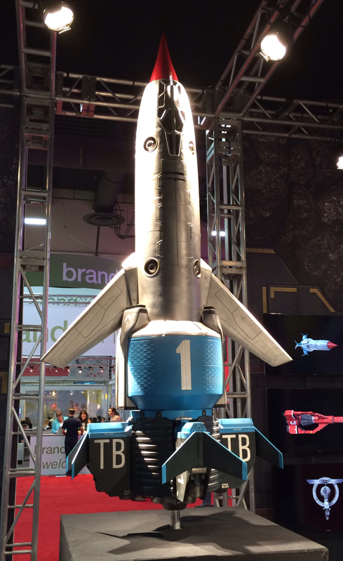
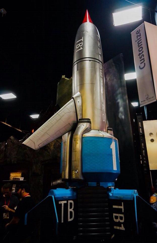
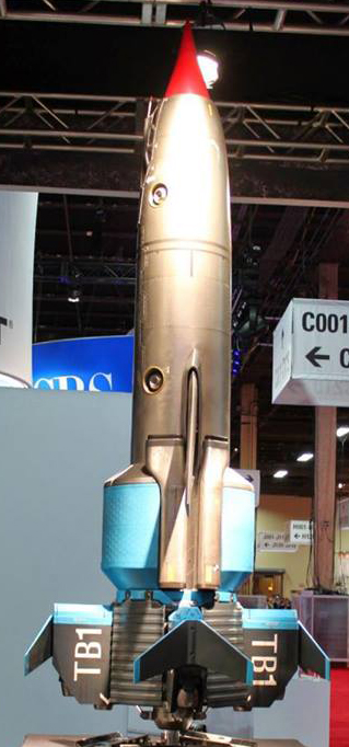
Luckily, WETA has been touring around the toy and merchandising conventions with a large 10 foot physical model of the ship too, and some photos gave me more information about shape and proportion, as well as detail.

tag-tb1-physical-model-underside tag-tb1-physical-model-02 tag-tb1-physical-model-01

And of further help, a friend of mine, Barry Kay, took some very nice high-rez close-up detail shots from various angles all around the model, which I used to work out a lot of the detail. (I may post those later.)
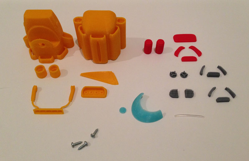
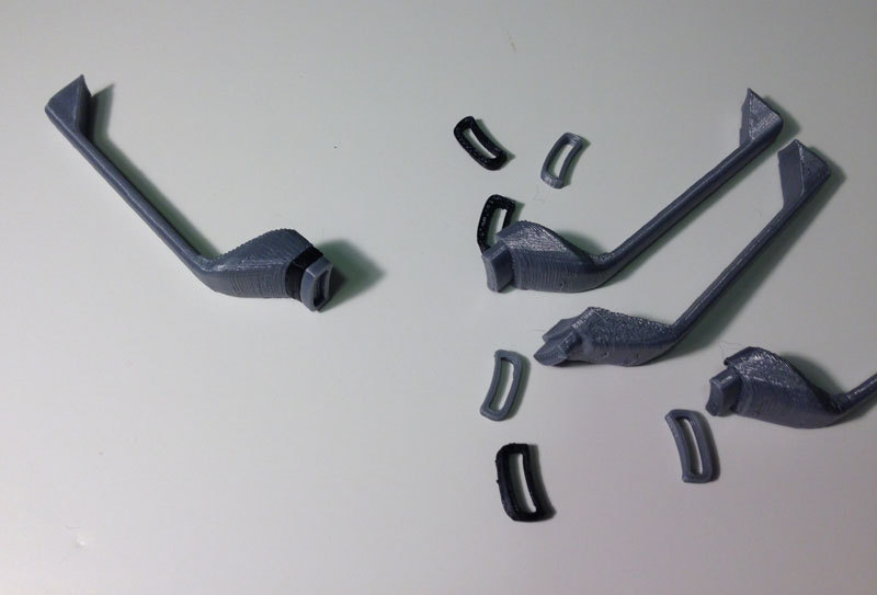
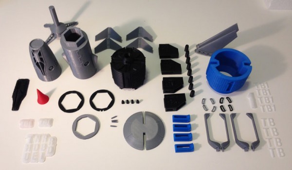
The Parts

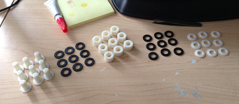
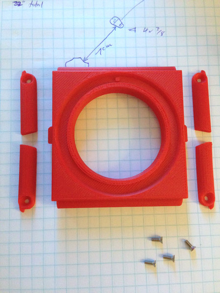
Here is a photo of all of the parts that make up this model. Note that there are 98 individual parts, including a display stand.
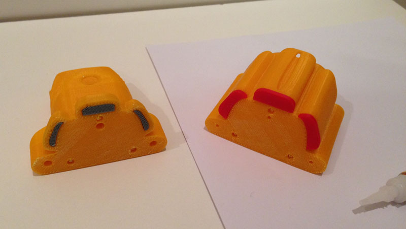
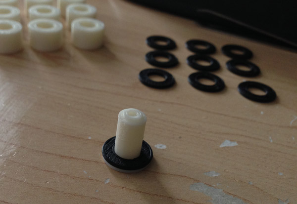
tag-tb1-3dprint-parts-all

The Main Body

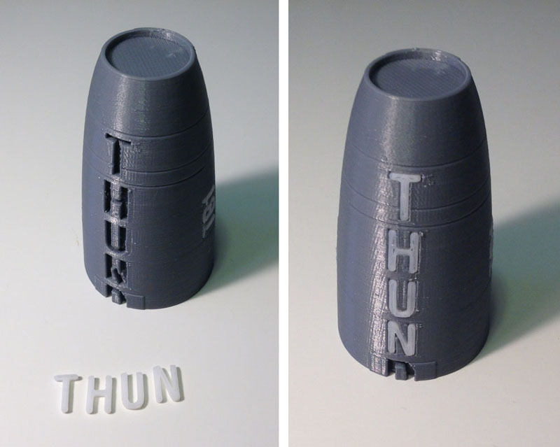
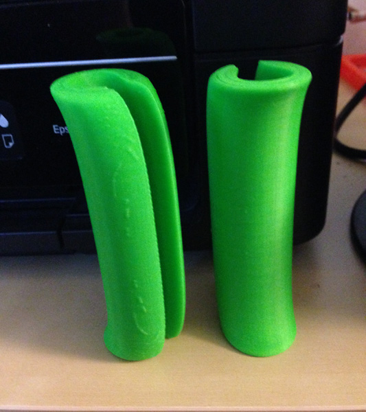
The main body tube is made up of five separate parts. These parts comprise the main tube in silver, and two stripes in black mid-body.

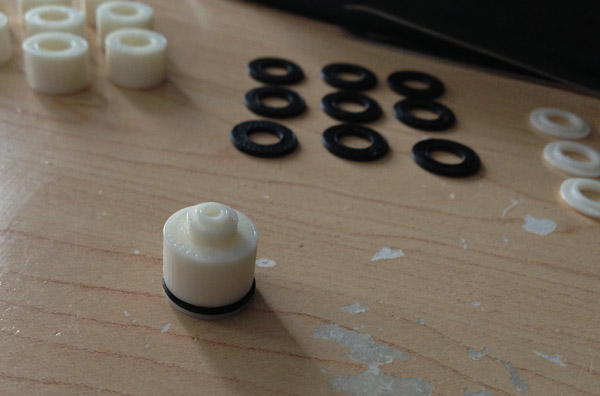
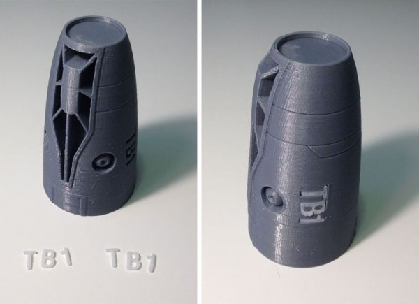
Here, the top section has two underjets, and cutouts for the cockpit windows and body text which will inlay as white pieces.

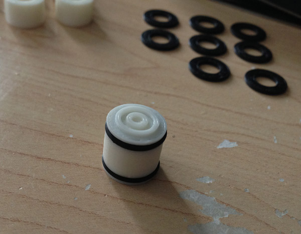
Here the side text is inlaid, so that the TB1 reads upright from either side of the body (only one side shown here.)

tag-tb1-3dprint-body-side-text-inlaid-01

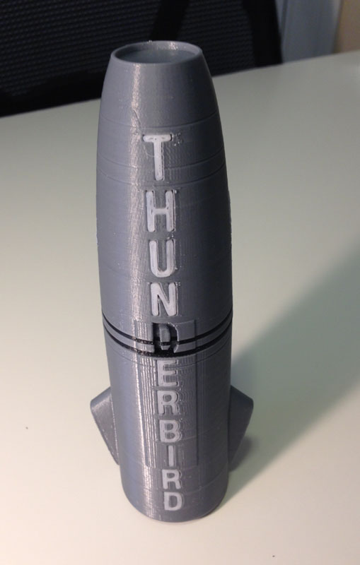
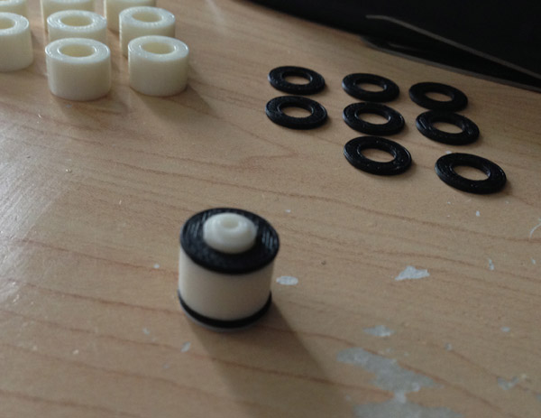
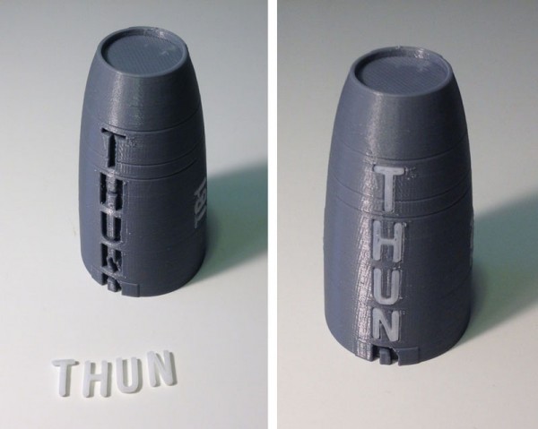
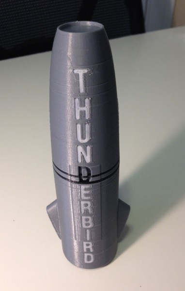
Then the topside of the body, which has the word THUNDERBIRD going down its entire length, is inserted, or at least the first few letters that are printed on this top section.

tag-tb1-3dprint-body-top-text-front-01

Then I do the same for the bottom body tube section:

tag-tb1-3dprint-body-bottom-text-01

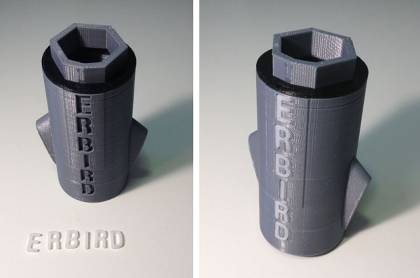
Next I attach the five main section pieces including the sandwiched black/silver/black rings, which leaves a hole for the letter D:
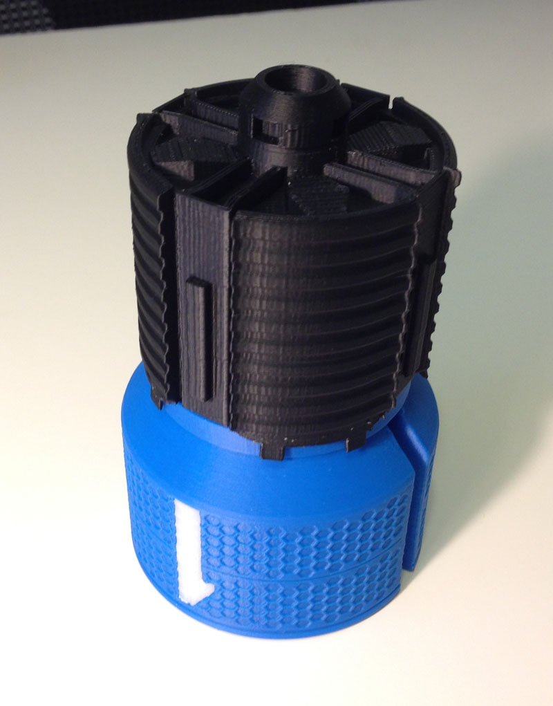
tag-tb1-3dprint-body-main-assembled-missing-d

The Engine Section

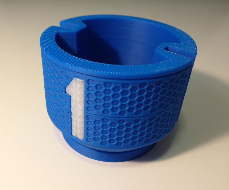
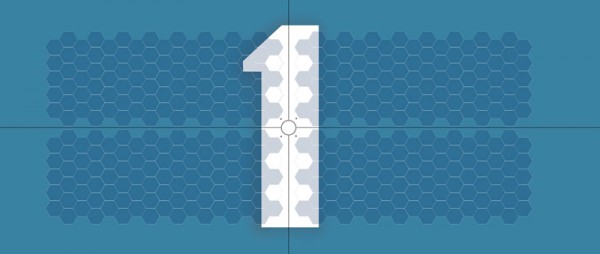
The blue section of the body, if you look closely, is honeycombed with hexagons. This was the most difficult part of this model to make, but it was oh-so-satisfying when it printed so nicely. I cut the large number 1 from it and made that an inlaid piece, but with the honeycombing intact.

tag-tb1-3dprint-body-section-1

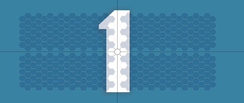
Here is an image someone posted of a texture used on this part of the body:

tag-tb1-cgi-body-detail

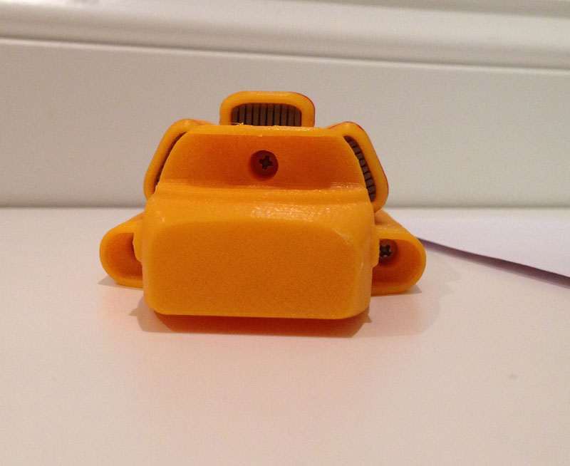
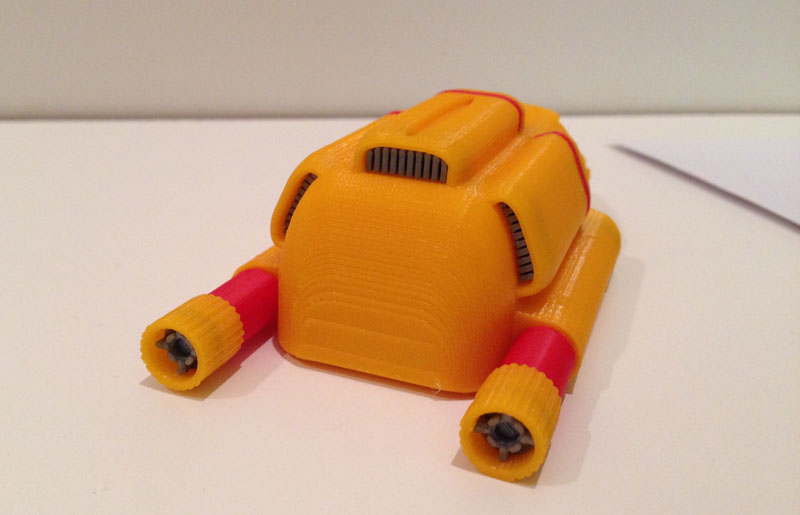
Here, I attach the large dark part, which looks like a heat sink, to the blue section. Note the detail on the bottom. This was not in any of the photos or CGI images I have seen.

tag-tb1-3dprint-body-rear-assembled

I got the detail from a rough GIF file someone posted of a turntable rendering of the ship that was on display on monitors next to the physical models at the conventions:

thunderbird-1

I snapped two frames of this GIF as it rotated and used them side-by-side to create a 3D parallax image (like a ViewMaster slide) and while the video has serious GIF dithering, I was able to make out some detail in depth, so I modeled in what I could see.

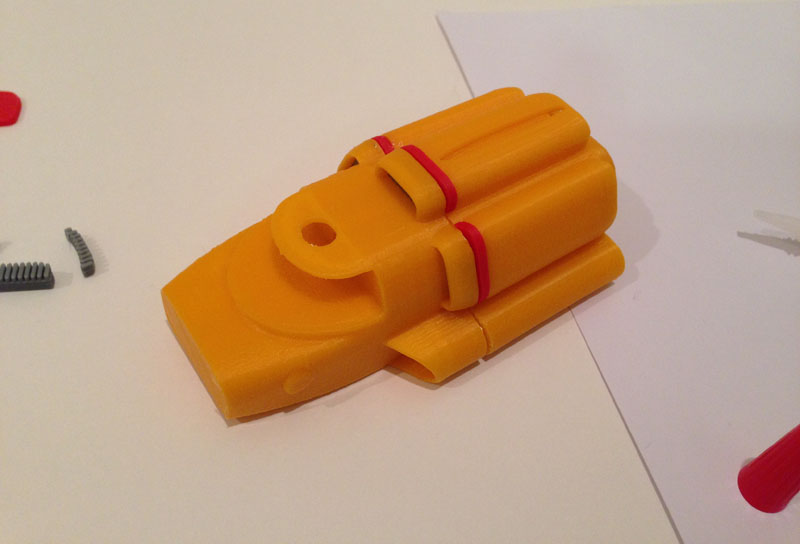
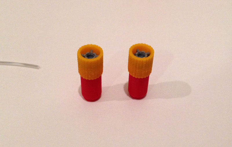
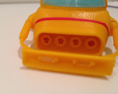
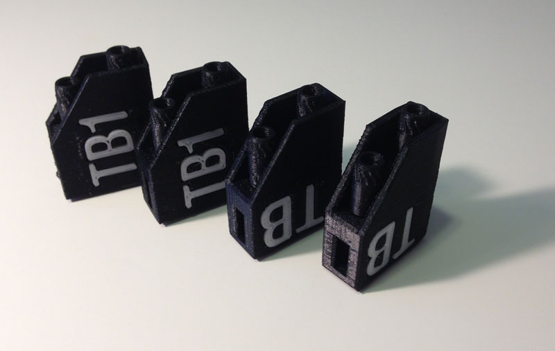
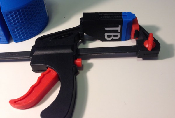
Next come the thruster housings for the 8 jet engines. Each housing has TB or TB1 (depending on which one) inlaid in, and two jet engines attached:

tag-tb1-3dprint-engine-housing-jets

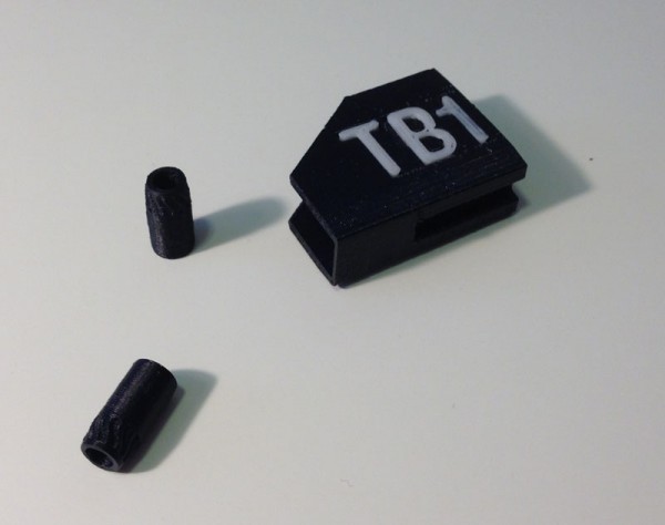
Here are the four housings:

tag-tb1-3dprint-engine-housings-done

I had a conflict here. While the rotating turntable image (posted above) clearly shows the TB1 as upright on the upper and lower housings, so when the ship is landed flat it reads correctly, the physical model my friend photographed showed the TB1 as reading upright relative to the body, so I decided to go with the physical model for now.

(To make that a changeable thing, I opted not to glue the bottom thruster housing in place. It snaps in rather well, so it holds. Later, I will reprint that one with the TB1 facing the way it faces on the CGI model.)

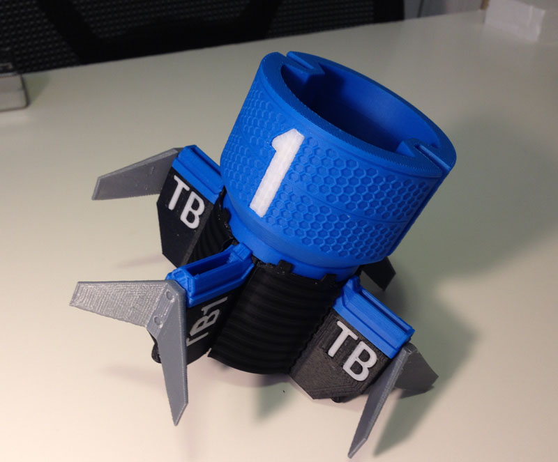
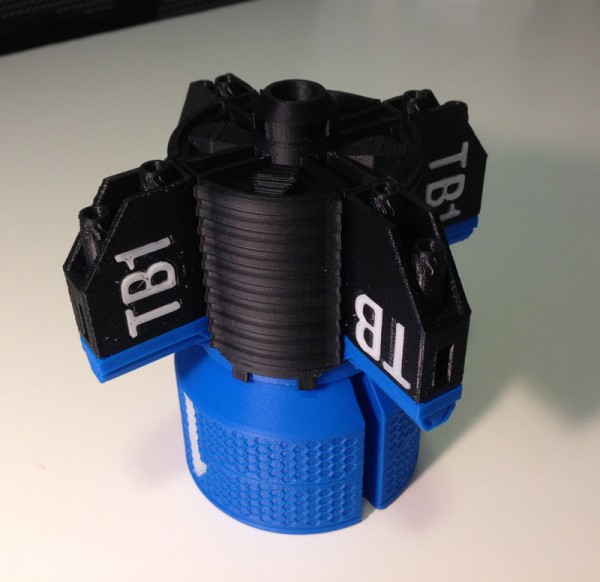
Then I added the blue jet intakes to the tops of each thruster housing:

tag-tb1-3dprint-engine-housing-intake-attached

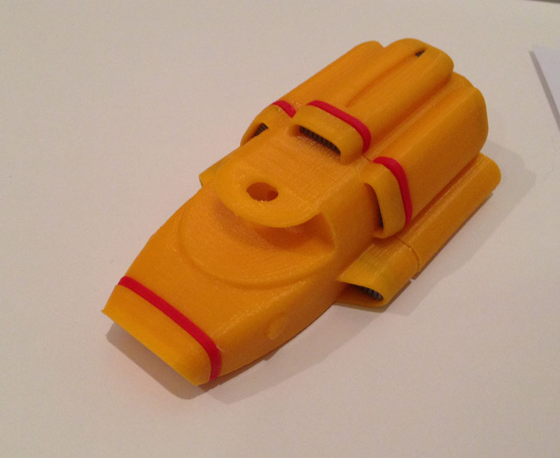
Then I added the housings to the heat sink section:

tag-tb1-3dprint-engine-housings-attached

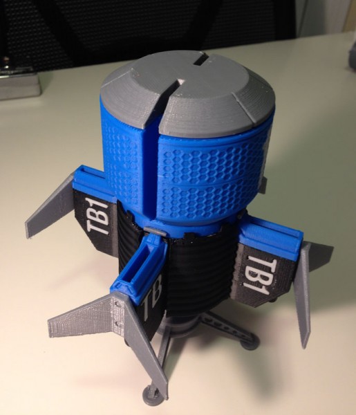
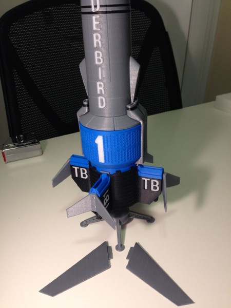
Next I added the fins

tag-tb1-3dprint-fins-attached

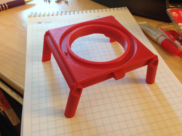
Then the flare section that connects the engine section with the body section, adding the silver pins to the tops of the thruster intakes. (Note the display stand, which is not canon. I just made it interesting.)

tag-tb1-3dprint-body-bottom-assemby

I then joined the two body sections together.

tag-tb1-3dprint-mostly-done

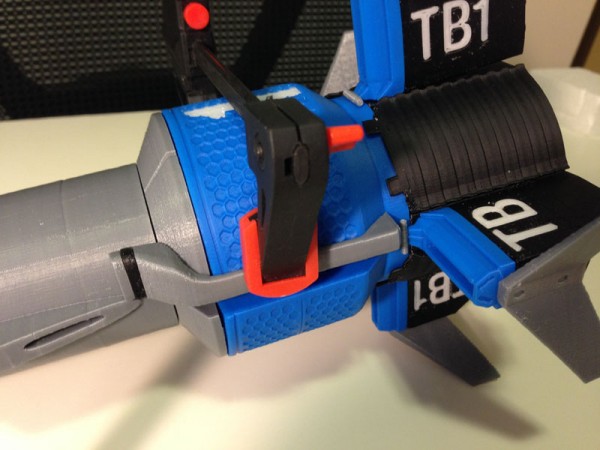
Next are the main engine intakes, each made from 3 pieces:

tag-tb1-3dprint-engine-intakes

These get attached next to the slots where the wings would retract:

tag-tb1-3dprint-engine-intakes-assembly

Last Bits

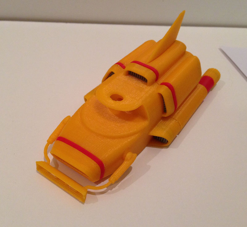
Then I prepared the wings, which have tabs that fit into slots in the body shoulders.

tag-tb1-3dprint-wings

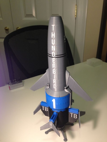
And here they are, slotted in place.

tag-tb1-3dprint-wings-assembled

(In a future version of this model, these wings will actually scissor out on gears, so they can retract, like they do on the show. But for now this will do. The wings on this model are static. Making them do what I hope to do later will be quite a complicated job, but one I hope to take on later this year.)

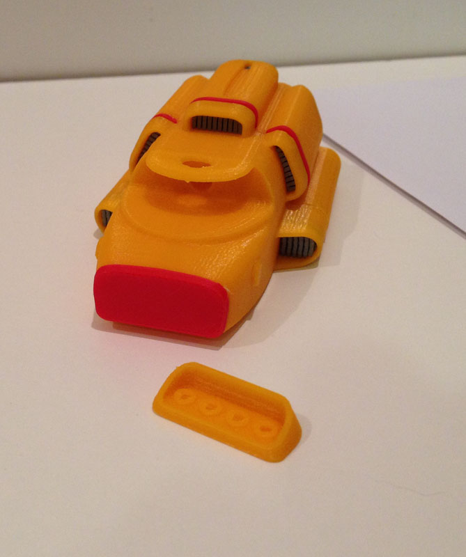
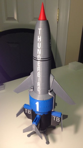
Almost the last part is the nose-cone:

tag-tb1-3dprint-fully-assembled-on-stand-topside

The very first image showing all of the parts has the window inlays printed in black. While I was assembling this model, I got a shipment with some glow-in-the-dark sky blue filament from Zen Toolworks, and I printed the windows again in that color to see if it worked better than black.

I also used a sample Zen sent me of translucent filament and tried that.

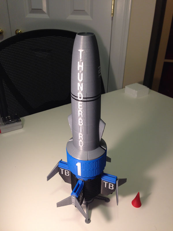
The winner was blue:

tag-tb1-3dprint-fully-assembled-on-stand-underside

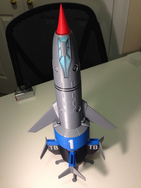
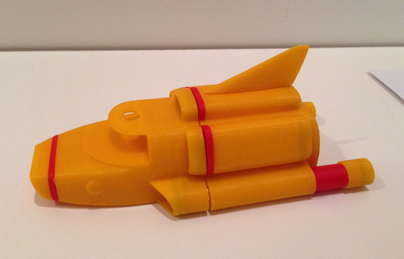
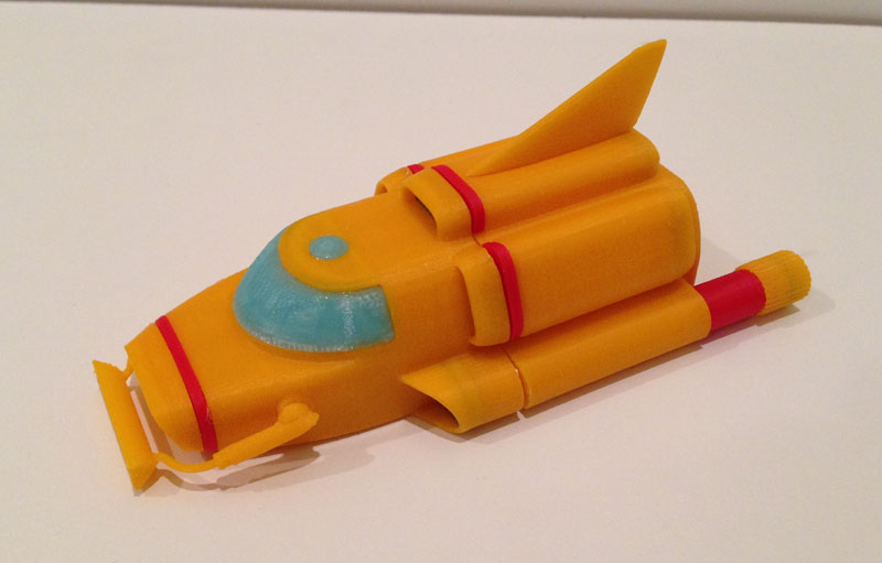
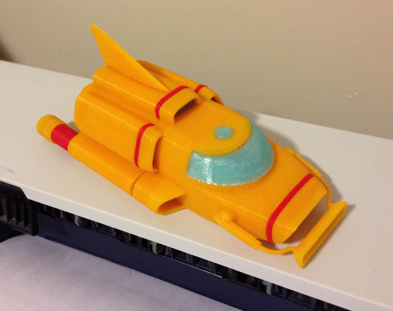
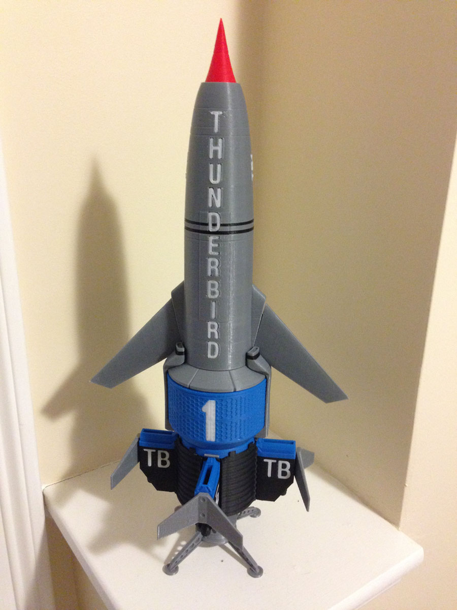
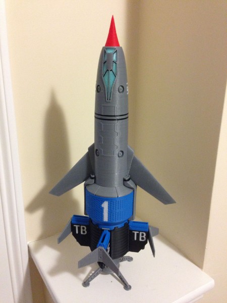
So there you have it. My version of WETA’s Thunderbird 1 from Thunderbirds Are Go.

Here it is on display:

tag-tb1-3dprint-fully-assembled-on-display-underside tag-tb1-3dprint-fully-assembled-on-display-topside

Still missing: The Pitot tube which juts from the cockpit area, and some other body detailing, which I hope to add when I make the retractable-wing version later.


Look What I Made!

A week or so the folks at Afinia said they were looking for some solid single-print models so I adapted some of my stuff for them, some useful, some less so.

One thing everyone wants to print is a robot so I made them a seamless single print robot model which I gave them to do with as they please. They sent me some filament in return which made me happy.

Here is the little guy: at scale he stands almost exactly 10cm tall.

IMG_2875.JPG

IMG_2873.JPG

IMG_2874.JPG

IMG_2876.JPG

Our House – Is A Very Very Very Fine House

We are currently (as of Nov 28, 2014) in the process of purchasing a house. Here is a photo of the house in question:

our-house-actual-01

For as long as we have been able, starting in the late 1980s, Carol and I have collected the Hallmark House series of Christmas ornaments, with a couple of gaps here and there when we simply could not afford to buy that year’s house (mostly in the first 7 years). But mostly we have the whole set, and it goes on the tree every year, with new ones added.

This year Carol asked me to make her a Christmas Tree Ornament of our new house, which we hope is where we will spend Christmas this year.

Here it is. Well, here’s two actually, since my Mother requested one as well.

our-house-ornament-pair-01

The wreaths indicate Christmas. I also modeled green gift bows for the roof but I’m not sure I want to use them.

But in keeping with my last year’s ornament, the Afinia printer:

cropped-afinia-ornament-assortment-large1.jpg

… I think I will put this year’s date on the roof.

This picture is of the first of my 3D Printed Ornament Series which I created last year. I sent the files to Afinia, the makers of my printer (at their request after I sent them an actual ornament) and they printed it out in a number of colors and then used this image for their front page image for a while.

Big Hero 6 – Baymax

On Friday I took a sphere, popped a lattice onto it and warped it. I did the same again to a different sphere, and pushed one into the other. Then I did a third. Then a fourth, which I bent like a piece of macaroni. I duped that one 2 times and placed those by the original. Then I made another that looked a bit like a Vienna sausage. Then I made a conical cylinder. After putting those last bits together I duped it and mirrored it. I then made another sphere and warped it with another lattice and duped it.

Then I made two cylinders, scaled them a bit on the X and rotated them a bit, and created a low, wide cube. I duped one of the spheres, enlarged it a bit, and used Boolean to cut a hole in that sphere shaped like the cylinders and cube.

To top it off I made another sphere, extruded it a bit, cut a line through it and bent the line a bit, and shrank it down to fit the first sphere.

Then I used a series of booleans to combine these objects, and in some cases to cut holes, and this is the end result:

baymax-model

And here is the printed result, standing about 12cm high including base, or about 4.75 inches.

baymax-printed-01

Total modeling time, just over an hour.

Total printing time, about 8 hours.

As an added feature I made two hexagonal posts on the base that fit into two hexagonal holes in the feet so he can stand firmly on the display base, but he can also stand on his own, since his feet are flattened.

UPDATE – Nov 28, 2014

A day or two later I decided to position Baymax in a new pose – handing out a lolly-pop, as he is seen doing in the movie. Also I added his charging/docking station in open mode as a new form of display stand. I changed the angles of the left hand’s fingers so they print more consistently.

baymax-trio-01


The Bot Shoppe Has Two New Robots! – Introducing Poe-Bot and HP Hovercraft!

The Bot Shoppe now has two new members: Poe-Bot is based on Edgar Allan Poe and features a raven (“The Raven”, a trowl (“A Cask of Amontillado”), and his body is heartshaped (“The Telltale Heart”).

bot-poe-bot-01

And his companion, HP Hovercraft is a new body design. Sitting atop a hovercraft motion system, HP Hovercraft has six tentacles with which to work his horrors. The be-tentacled body spins!

bot-hp-hovercraft-01

This now the seventh robot in the Bot Shoppe.

bot-shoppe-lineup-2014-11-08

I Won! I Now Have Two 3D Printers!

A while back I posted that I had entered a contest at 3DAGOGO and won a Makerbot Digitizer, a 3D optical scanner. I was thrilled and I gave the machine several test runs. I was not overly happy with the resultant scans. I sold the scanner. I may get one later when the tech becomes something more reliable and accurate.

But that didn’t stop me from entering another contest. “What Would You Print?”

The idea was to submit useful, practical designs (by sending a printable file) and a panel would judge the winners based on practicality, usefulness and ease to print.

I submitted two designs that I came up with quite some time ago:

1) Grocery bag handles. One of the things I wanted to print with my printer even before I got one was a grocery bag holder that would help me carry more plastic grocery bags (and can handle cloth bags too) so my hands (which hurt when I carry too much weight with so little surface area) wouldn’t hurt when I carried groceries in from the car.

grocery-bag-handles-green-01

A simple design. Bag handles go into the slot, and you hold the handle. I find I can carry plenty of weight, but what the scrunched-up plastic handles do to my fingers makes the carrying much harder. This way there is no stress on my individual fingers, and I can carry double the weight in groceries per hand. The space is wide enough to accommodate cloth bag handles too.

2) A switch protector plate for the garbage disposal on our sink. The switch is under a cabinet and is hard to see unless you lean down. There are two switches on a common plate and I can’t count the number of times I turned on the disposal when I intended to turn on the light. So this plate now sits over the disposal switch and makes it impossible to turn on the disposal by accident. You have to slide your finger in between the two guard rails to use it.

switch-protector-red-01

You simply remove the two screws, place this plate directly over the switch you want to protect, and screw the screws directly back in place. No expertise needed. And now to use the switch you have to be very deliberate. You simply cannot accidentally turn on the disposal.

Apparently both of my entries were in contention for a prize. This video announced the entries.

Then I got an e-mail congratulating me on winning second prize – a RioTBoard, which is a circuit project board that allows you to make any number of electronic projects. I was reasonably excited. I began to look forward to trying out some projects.

Not long after that I got an e-mail apologizing. They claimed they got the e-mails mixed up. Apparently I had not won second prize, I had won First Prize!

I had actually won Grand Prize which was an Afinia H480 printer!

The Afinia H480 is the next model up from my own Afinia H479 printer which I have had for a year and a half and have loved since I got it.

The Afinia H480 is essentially the same printer with some extra features including a print bed with springs to hold down a print plate, and an auto-calibration system.

With the Afinia H479 you calibrate the board by rotating three set screws holding the plate in place. You use the Mainenance Panel in the software to raise the print bed up to meet the nozzle and leave .2mm of room between the nozzle and the plate in all four corners and the center. When you can slip a standard file note card under the nozzle cleanly (not too tight, but you can feel the drag on the nozzle) you have calibrated the bed.

I find calibration stays set for quite some time. A knock or an accidental print incident that moves the bed could pull it out of calibration, but it’s not something you have to do daily, or even weekly, usually.

But if you want to ensure a good calibration, the H480 allows you to attach a calibration switch to the print head and use the software to level the bed and detect nozzle height. Note that this appears to be a software leveler. It does not level the bed, it just detects the tilt of the bed and prints to that angle, I believe.

Watch this video from 1:30 onward to see how the calibration and nozzle height detection works.

But I can’t tell you how thrilled I was to find I had won another Afinia printer. I sometimes do projects that require a lot of printing and being able to have two running at once will really cut down my print times on larger print runs.

Dinky Scaled Freighter/Pallet Pod Containers

In Space 1999’s first episode “Breakaway” we see Eagles transporting nuclear waste containers in freighter or winch pods for storage on the dark side of the moon. When the nuclear material begins to become unstable, winch pods are used to distribute them to alleviate the approaching critical mass.

eagle-unloading

Here are a few of the real Nuclear Waste Canisters as seen in the episode:
eagle-nuclear-waste-canister

Here is someone’s (sorry, I forget who. If you know, I would like to attribute it to the proper person) custom-made Freighter/Pallet pod made from parts of the Product Enterprise Eagle, to fit those models:
eagle-freighter-pallet-pod-real

A couple of months back I spent some time modeling a Winch Pod and a Freighter/Pallet Pod for my 4″ Konami Eagles and also for my 10″ Dinky Eagles.

One thing I modeled was the nuclear waste container. It was a single piece, a fairly simple 3D printed cylinder, with rings and a cap. I would paint the rings and create my own water-slide decals to give them the warning label the canisters had.

dinky-freighter-canisters-plain-painted-01

You can see I found painting the black rings to be quite difficult. Getting anything consistent or even was near impossible for me. I’m not that skilled at painting models.

So I decided – hey, I have a 3D printer after all, I don’t have to print these as a single piece. In fact I can print them in two colors in their individual rings.

So I set out to break the simple model down into a base with a post (that also forms the center of the cap at the top) with two black rings, a central body section, and a cap.

dinky-freighter-canisters-all-pieces

Here, the first black ring is slipped on over the base post/cap:
dinky-freighter-canisters-bottom-ring

Then the central body ring slides on:
dinky-freighter-canisters-body

Flanked by the top black ring:
dinky-freighter-canisters-top-ring

Topped off with a white cap that snaps to the central hub:
dinky-freighter-canisters-cap

I used clamps to hold them while the Super Glue was drying. Then I applied water-slide decals I designed and printed myself.

Here you see the painted version on the left and the printed version on the right: (I think I can probably thin out the rings a bit…)
dinky-freighter-canisters-painted-vs-printed-02

And here is what the finished Dinky Pallet/Freighter Pod looks like:

dinky-freighter-canisters-loaded

NOTE: For anyone who buys these models from me at my shop (Fourth D) on Shapeways, you may want to print the decal sheet I created. The two links below are to PDF files you can print.

Pod-Decals-Better-Layout

Pod-Decals-Instructions

You can print them on white waterslide paper either in laser or inkjet (make sure you have the right paper and follow instructions that come with the paper) or you can print them on simple white paper and use simple glue if you like. The decal sheet has both the Konami and Dinky scaled decals. Also, the instructions for the decals (for waterslide) are available here.


Adventure Team Backpack Surveillance Drone – Now in AT Colours

Last year I posted an article about my 3D printed Adventure Team set, the Action Pack Backpack Drone Surveillance. I designed it and 3D printed it on my Afinia H479 printer. Originally the drone was white with black structure and red highlights. The backpack was orange and black. These are acceptable Adventure Team colors.

at-drone-backpack-launch-base

But I decided I wanted to see how it looked in the more typical Adventure Team colors of red and yellow. I bought some Afinia Premium Red filament for the first time. (I had some Afinia Premium Yellow before, and I printed my Backpack Jetpack with that material.)

The result is pretty nice:

at-drone-backpack-with-drone-complete-01

Note: To apply my laser-printed water-slide decals I had to do some experimentation. These decals do not stick to ABS plastic. I discovered that spray-painting the top part with a satin clear coat paint, the decals would stick pretty well. Another spray coat over it and it should seal them down nicely. (Of course rough treatment may still make them come off.)

The Parts and Assembly

You saw how the drone was assembled (though in a slightly smaller scale it is an identical process) in my post about the Cotswold Deluxe Midnite Mission set.

The backpack frame, legs and screws:
at-drone-backpack-parts-01

The legs form the side of the backpack when being carried, and support the frame as a launch platform for the drone when in use:
at-drone-backpack-legs-assembled-01

Next, the harness. It is comprised of a 22-inch strip of .375 inch wide black elastic. First, I fold the elastic in the middle and place it into the space modeled into the harness bracket front half. While this picture does not show it, the red half has a channel modeled to fit the elastic on a folded angle.

at-drone-backpack-harness-parts-01

Then the two short, stubby screws are screwed into the black back plate through the elastics to hold it firmly:
at-drone-backpack-harness-screws-01

Here are the four black strap brackets that will hold the elastic harness in place on the frame:
at-drone-backpack-harness-brackets-01

The elastic is carefully placed so there is a 7cm distance between the top bracer and the harness chest piece. A screw holds the elastic and the bracer in place firmly. Then the elastic is stretched somewhat (consistently) to the lower bracer and that is screwed onto the frame. There is equal tension between the two bracers for a purpose:
at-drone-backpack-harness-attached-01

Next the strap adjuster and harness clips are placed onto the elastic strips:
at-drone-backpack-strap-adjusters-01

The completed harness:
at-drone-backpack-harness-complete-01

Next, the solar cell (which charges the drone’s recharging batteries when it is in the air) is glued to the circular aperture:
at-drone-backpack-solar-cell-01

On top of this the drone’s holding tray is glued: The drone fits perfectly between the three clips, and the top clip is used to free it by pressing gently until the drone is released from the grip of the tray.
at-drone-backpack-drone-tray-01

Here you see the touch-screen tablet used to fly the drone, and to monitor the drone’s camera capturing ability. This is a single printed piece with clear-coat and a glossy printed screen spray-glued (with permanent glue hopefully) to the surface:
at-drone-backpack-control-tablet-01

Ok, I’m going to claim some cleverness now. This tablet stores perfectly flat in the backpack frame in a cavity modeled to fit it, held in place by the harness straps:
at-drone-backpack-tablet-storage-01

Here it is, stored fully:
at-drone-backpack-tablet-stored-01

Lastly, for the backpack, these four black “bolts” are glued onto the legs (so as not to interfere with the screws) to finish off the look:
at-drone-backpack-leg-bolts-02

Et voila:
at-drone-backpack-with-drone-complete-01